Download
1 / 21
310 likes | 1.29k Vues
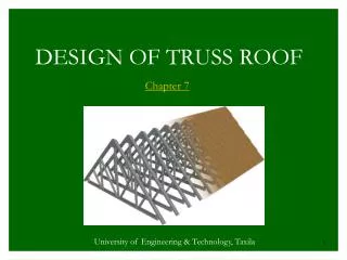
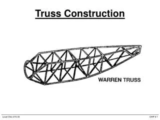
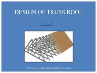
Chapter 7. DESIGN OF TRUSS ROOF. University of Engineering & Technology, Taxila. LOADS ON TRUSS ROOF

E N D
Chapter 7 DESIGN OF TRUSS ROOF University of Engineering & Technology, Taxila Prof Dr Z. A. Siddiqi
LOADS ON TRUSS ROOF All the gravity or vertical loads acting on the building trusses are first calculated in terms of the loads acting per one square meter of the horizontally projected area (plan area) having the units kg/m2, N/m2 or kN/m2. The wind loads are calculated per square meter of the actual inclined roof surface in the same units. Prof Dr Z. A. Siddiqi
Dead Loads Dead load is the self weight of different components of the structure itself. Its magnitude and point of application does not appreciably change with time. Dead load on a truss will comprise of loads of roof coverings, perpendicularly running beams (purlins), connections, supporting elements (braces) and self load of the truss. Prof Dr Z. A. Siddiqi
Superimposed Loads All the loads externally acting on the structure leaving its own weight are called superimposed loads. The expected maximum loads are called service loads and the design loads for LRFD method are the loads obtained after multiplying with the appropriate load factors. Live load, wind load, snow load and earthquake load are all examples of superimposed loads. Prof Dr Z. A. Siddiqi
Dead Loads of Truss Roof Components • The weights of various structural components per unit plan area are as follows: Prof Dr Z. A. Siddiqi
To obtain a better estimate of the truss self-weight for a 4 m spacing of trusses and a pitch of 1/4 to 1/5 with corrugated sheeting, weight per unit area of plan may be taken as • whereas for all other cases, the following formula may be used • Thayer Formula Prof Dr Z. A. Siddiqi
where • W = weight of truss (kg/m2) • w = Total load per horizontal plan acting on the truss (kg/m2) • S = spacing of truss (m) • L = span of the truss (m) Prof Dr Z. A. Siddiqi
Snow Loads • Snow load is calculated according to maximum expected depth of snow in a particular locality and density of snow. • Maximum density of snow = 786 kg/m3 • The density of snow significantly varies with the amount of compactness. Prof Dr Z. A. Siddiqi
Live Load (or Minimum Snow Load) • The minimum live load for various situations is given below: • 100 kg/m2for θ ≤ 10° for no access to roof • 200 kg/m2for θ ≤ 10° when access to roof • (113-1.3θ) kg/m2for 10°< θ ≤ 20° • (143-2.8θ)kg/m2for 20°< θ ≤ 30° • 60 kg/m2for θ > 30° Prof Dr Z. A. Siddiqi
Wind Load • Windward side – face towards wind • Leeward side – face opposite to wind Windward side Leeward side θ Wind Direction Prof Dr Z. A. Siddiqi
Design wind pressure P = CeCqqsIw • where Ceis the combined height, exposure and gust coefficient • In open areas and for height up to 10 m Ce= 1.25 • 10 to 20m Ce= 1.45 • 20 to 30 m Ce= 1.61 • qs= wind stagnation pressure at st. height of 10 m. • = 0.0475V2 (N/m2) • where V= basic wind velocity in km/h • Iw= 1.0 for ordinary buildings Prof Dr Z. A. Siddiqi
P = 1250 Cq (N/m2) • for V=145 km/h and height up to 10m in open areas • Value of Pressure Coefficient (Cq) • Windward roof θ = 0° to 9.5°Cq = 0.7 outward (-) • 9.5° to 37°Cq = 0.9 outward or • 0.3 inward (+) • 37° to 45° 0.4 inward • >45° 0.7 inward Prof Dr Z. A. Siddiqi
Leeward or flat roof 0.7 outward (-) • Windward walls 0.8 inward up to 6m height • 0.87 inward for 6 to 12m height • 1.0 inward for 12 to 18m height • Leeward walls 0.5 outward up to 6m height • 0.54 outward for 6 to 12m height • 0.63 outward for 12 to 18 height Prof Dr Z. A. Siddiqi
SELECTION OF MEMBERS OF ROOF TRUSS • For riveted and bolted trusses a pair of angles back-to-back is the most common type of member. • For short spans and lightly loaded trusses, a single angle is sometimes used, mainly for tension members. • Equal and unequal angles both should be checked and that angle should be selected which satisfies minimum weight and slenderness requirements. • It should be remembered that the single angle member does have the disadvantage of eccentricity and should properly be considered in the design of these members. Prof Dr Z. A. Siddiqi
SELECTION OF MEMBERS OF ROOF TRUSS • For larger riveted or bolted roof trusses T, W, M, S, or two channels back-to-back sections may be used for some of the members. • The two sections of the members are connected at intervals by filler plates (stay plates) with welding or riveting to give slenderness ratio of single section (where the two sections are not joined) lesser than the slenderness ratio of the double section. Prof Dr Z. A. Siddiqi
SELECTION OF MEMBERS OF ROOF TRUSS • A minimum size member for practical reasons to avoid too flimsy sections is often L51 х 51 х 6.4 or an equal area equal to this section. • An effort should be made to limit the width of the truss members because it has been found that trusses with very wide members tend to have very large secondary forces. • If structural T is used as top chord member for a welded truss, gusset plates may be unnecessary for top chord and web members can be welded directly to the stems of tees. Prof Dr Z. A. Siddiqi
SELECTION OF MEMBERS OF ROOF TRUSS • The chord members of roof trusses often consist of one section which is continuous through several panel points. • This may be designed for the maximum force in any of the parts in which it is continuous. • This practice may seem to be uneconomical, but considering the resulting saving in the cost of the splices, the result may be an economical design. If splices have to be made at certain points for shipping or handling purposes, sizes may be economically changed at those points. Prof Dr Z. A. Siddiqi
Selection of Truss Members using Angle Sections • For top chord members which are adjacent to each other and have a force up to 25% lesser than the maximum out of these members, same section could be used which is designed for the maximum force member. • However, for all other top chord members, same depth section should be selected. • Same procedure applies to bottom chord members. Prof Dr Z. A. Siddiqi
Selection of Truss Members using Angle Sections • The corresponding members on left and right of the truss should be designed for maximum force because the hinge and roller support may be used on windward or leeward side. • All top and bottom chord members should be double angles. • All compression members should be double angles. • Web tension members may be single or double angles depending upon the magnitude of force. Prof Dr Z. A. Siddiqi
Selection of Truss Members using Angle Sections • Zero force members should be single angles. • Stay plates spacing should be calculated for all double angle sections. 4 4 5 5 3 3 1 1 6 2 2 Correspondence of Truss Members for Design Prof Dr Z. A. Siddiqi