Download
1 / 15
150 likes | 240 Vues
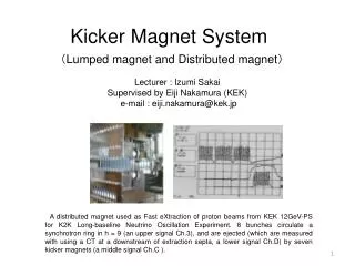
Nov. , ’08 KEK H. Yamaoka. Support system of final quadrupole magnet in a Detector. Contents Introduction Calculations Installation Conclusions. QD0 (700kg). BeamCAL (100kg). LHCAL (3000kg). 750. LumiCAL (250kg). 6000. ECAL (420kg). Introduction. ‘MDI at GLD’ by Y. Sugimoto

E N D
Nov. , ’08 KEK H. Yamaoka Support system of final quadrupole magnet in a Detector • Contents • Introduction • Calculations • Installation • Conclusions
QD0(700kg) BeamCAL(100kg) LHCAL(3000kg) 750 LumiCAL(250kg) 6000 ECAL(420kg) Introduction ‘MDI at GLD’ by Y. Sugimoto ILD Workshop at DESY, Zeuthen Components of IR- region are planed to support with the Support tube. Cylindrical Support Tube Strength, Installation scheme will be presented.
BeamCAL: 100kg • Boundary conditions; • -Models • - Half-Cylinder • - Full-Cylinder • - Half-cylinder with reinforcement ribs • - Thread Bolts connection • -FEM analyses • ・Static analysis • ・Modal analysis • ・Dynamic load such as ground motion • - Materials • - Stainless steel • - Aluminum • Load condition • See: right-upper • -Constraints • - Only cylinder’s end. • (Cantilever) LHCal: 3000kg LumiCal: 250kg ECal: 420kg Fixed QD0: 700kg Self-weight
Results Static analysis • Half-cylinder • Stainless-steel • 50mm-thick deformation: 20mm • Deformation(Static)=20mm • The deformation is too large. Fixed • Half-cylinder with reinforcement ribs. • Stainless-steel • 50mm-thick • Each weight + Self-weight • Deformation(Static)=8.5mm • The deformation is also large. • Complicate fabrication. Support tube should be full-cylinder.
BeamCAL: 100kg LHCal: 3000kg LumiCal: 250kg ECal: 420kg Fixed QD0: 700kg Self-weight ・Full-Cylinder is assembled from two half-cylinders Supp. tube= 50mm-thick. 24-M24 • - Materials • -Stainless steel or Aluminum • Load condition • See: right-upper • -Assumptions • - Fixed only cylinder’s end (Canti-lever). • - Bolt pre-tension was defined. • - Defined slide on the boundary of half-cylinders. 500mm
Results Static analysis • Full-cylinder assembled from two half-cylinder. • Stainless-steel • 50mm-thick • Each component weight +Self-weight deformation: 6mm - 3.2mm(Full cylinder) - 20mm(Half-cylinder) Fixed
Natural frequencies 1st mode: 9.6Hz 10Hz(Full cylinder) 4Hz(Half-cylinder) 2nd mode: 81Hz 3rd mode: 111Hz
Amplitude due to ground motion Vertical-dir. @KEK: ATF(17:00 Feb. 10, 2004) 2x10⁻⁷m/s2 Linear Spectrum FFT - Input Acc. : a= 2x10⁻⁷m/s2 - Mass: m=(5411.5+700+100+3000+250+420)/9.8[m/s2] - Damping ratio=2% Self-weight F0cos(wt)=(m・a)sin(wt) F0=2x10⁻³N w= 0 – 1000Hz ・Input Acc. is the measurement data at ATF in KEK. ・Input data is assumed to be harmonic vibration.
Calculation result 2.7nm (@9.6Hz) The maximum amplitude: 2.7nm @ 9.5Hz(1st mode)
Installation scheme ‘MDI at GLD’ by Y. Sugimoto ILD Workshop at DESY, Zeuthen Initial condition
1. 2. Tension rods Scaffold Timbers • Top of the support tube is supported by tension-rods. • or, It is supported by timbers at the bottom. • 20mm sagged in case of the half-cylinder. - Temporal rigid scaffold is set on the floor. - The bottom half-cylinder is connected.
4. 3. Calorimeters QD0 - Set Calorimeters. (a) Set chain hoist on the inner cryostat. or (b) Assemble support frame on the temporal scaffold. - QD0 is lifted by crane. - Set it to the correct position.
5. 6. - Upper support tube is lifted by crane. - Set it to the correct position. • Remove the temporal scaffold. • Finished.
Stiffness at the support position (Full-cylinder) Fixed! (Full-cylinder) Fixed 3.2mm 4.5mm • Deformation is 40% increased. 3.2mm 4.5mm(Full cylinder) 6.0mm 8.4mm(Estimation: Bolts connection) • There must be some ideas to increase the stiffness at the support position.
Conclusions - Half-cylinder is too large deformation. Support tube should be assembled to full-cylinder. - Adequate material for the support tube is supposed to be stainless steel. Smaller deformation/stress rather than aluminum case. CFRP/Tungsten for the support tube is not realistic. - Amplitude due to the ground motion is a few nm. It is necessary to check whether it’s acceptable or not. - Preliminary installation scheme was thought. This scheme should be made more realistic. End