Pipeline Control
270 likes | 296 Vues
Learn about updating control lines in each cycle, setting control values in each pipeline stage, and managing hazards in pipelined datapaths. Explore structural, data, and control hazards and resolutions.

Pipeline Control
E N D
Presentation Transcript
Pipeline Control \course\cpeg323-08F\Topic6b-323
Assumptions • PC is updated at each cycle. • Pipeline registers are also updated at each cycle. • Only need to set control values during each pipeline stage. \course\cpeg323-08F\Topic6b-323
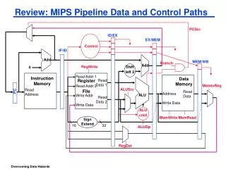
Control lines See P&H Fig. 6.23 3rd Ed. or 4.46 4th Ed. \course\cpeg323-08F\Topic6b-323
Five Groups of Control Lines • Instruction Fetch: The control signals to read instruction memory and to write the PC are always asserted, so there is nothing special to control in this pipeline stage. • Instruction Decode/Register Fetch: As in the previous stage, the same thing happens at every clock cycle, so there are no optional control lines to set. • Execution: The signals to be set are RegDst, ALUOp, and ALUSrc. The signals select the Result register, the ALU operation, and either a register or a sign-extended immediate for the ALU. \course\cpeg323-08F\Topic6b-323
Five Groups of Control Lines (Cont’d) • Memory Stage: The control lines set in this stage are Branch, MemRead, and MemWrite. These signals are set by the branch equal, load, and store instructions, respectively. • Write Back: The two control lines are MemtoReg, which decides between sending the ALU result or the memory value to the registers, and RegWrite, which writes the chosen value. \course\cpeg323-08F\Topic6b-323
ALU control input See P&H Fig. 6.23 3rd Ed or 4.47 4th Ed ALU control bits are set depending on the ALUOp and the different function codes for the R-type instruction. \course\cpeg323-08F\Topic6b-323
Function of control lines See P&H Fig. 6.24 3rd Ed or 4.48 4th Ed \course\cpeg323-08F\Topic6b-323
Value of control lines See P&H Fig. 6.25 3rd Ed or 4.49 4th Ed ALU control bits are set depending on the ALUOp and the different function codes for the R-type instruction. \course\cpeg323-08F\Topic6b-323
Control Lines for the Final Three Stages See P&H Fig. 6.26 3rd Ed or 4.50 4th Ed \course\cpeg323-08F\Topic6b-323
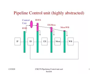
Pipelined Datapath with control signals See P&H Fig. 6.27 3rd Ed or 4.51 4th Ed The control values for the last three stages are created during the instruction decode stage and then placed in the ID/EX pipeline register. The control lines for each pipe stage are used, and remaining control lines are then passed to the next pipeline stage. \course\cpeg323-08F\Topic6b-323
Hazards and Hazards Resolution • Hazards • Hazards detection • Hazards resolution \course\cpeg323-08F\Topic6b-323
Hazards (cont’d) Situations that prevent the next instruction in the instruction stream to be executed at the designated clock cycle. \course\cpeg323-08F\Topic6b-323
Hazards (structral and data) (cont’d) • Structural: Resource conflicts when hardware cannot support all possible combinations of instructions in simultaneous overlapped execution. • Data: Instructions depend on the results of a previous instruction in a way that is exposed by the overlapping execution. \course\cpeg323-08F\Topic6b-323
Hazards (control) (cont’d) • Control: Due to branches and other instructions that change PC. Hazard will cause “stall”, but in pipeline “stall” is serious - it will hold multiple instructions. It stalls later instructions, not earlier instructions. \course\cpeg323-08F\Topic6b-323
Hazards (cont’d) Structural Hazards • Non-pipelined FUs • One port of a R-file • One port of M. • Othes ? Data hazards • for some data hazards ( e.g. ALU/ALU ops): • forwards (bypass) \course\cpeg323-08F\Topic6b-323
Data Hazards (cont’d) for others: pipeline interlock + pipeline stall (bypass cannot do on time) Lw $t1, 0(t3) Add $t4, $t1, $t5 This may need a “stall” or bubble \course\cpeg323-08F\Topic6b-323
Example of Structural Hazard \course\cpeg323-08F\Topic6b-323
PC ID EX MEM WB IF M R a ALU op IF ID EX MEM WB PC Unit 1 R 1 1 ALU 1 ALU OUTPUT 1 1 M 1 1 \course\cpeg323-08F\Topic6b-323
Data hazard example See P&H Fig. 6.28 3rd Ed or 4.52 4th Ed Pipelined dependencies in a five-instruction sequence using simplified datapaths to show the dependencies. \course\cpeg323-08F\Topic6b-323
The dependencies between the pipeline registers move forward in time, so it is possible to supply the inputs to the ALU needed by the AND instruction and OR instruction by forwarding the results found in the pipeline registers. See P&H Fig. 6.29 3rd Ed or 4.53 4th Ed \course\cpeg323-08F\Topic6b-323
Data Hazard Resolution • Software method • Architecture features \course\cpeg323-08F\Topic6b-323
Flow Dependency (R/W conflicts) A B + C . . . E A + D \course\cpeg323-08F\Topic6b-323
Output Dependency (W/W conflicts) A B + C . . . A B - C Leave A in wrong state if order is changed \course\cpeg323-08F\Topic6b-323
Anti Dependency (W/R conflicts) X A + B . . . A C + D \course\cpeg323-08F\Topic6b-323
How about arrays? . . . A [i] = = A[i-1]+… \course\cpeg323-08F\Topic6b-323
Data Dependence j i MIPS Read / Read Write / Write no Read / Write yes Write / Read no “Shared Datum” conflicts \course\cpeg323-08F\Topic6b-323
Data Dependence S1 Flow-dependence Output-dependence Anti-dependence S1: $R1 = $R2 + 1 S2: $R3 = $R1 + $R4 S3: $R4 = $R1 – 2 S4: $R3 = 2 S2 o Dependences: S1, S2 flow-dependence S1, S3 flow-dependence S2, S3 anti-dependence S2, S4 output-dependence 0 S3 S4 \course\cpeg323-08F\Topic6b-323