Download

1 / 53
570 likes | 799 Vues
Explore the evolution of the smelter operations at Mopani Copper Mines from 1937 to present, including furnace installations, production capacities, and environmental improvements.

E N D
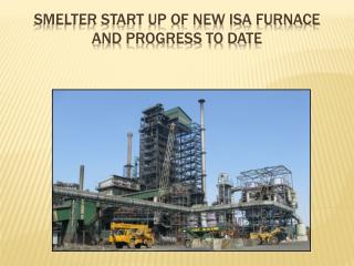
Mopani Copper Mines Smelter start up of new ISA furnace and progress to date
Smelting at Mufulira - Developments • 1937 • 2 x Reverbs, 4 x PS Converters • 1956 • 3 x Reverbs, 5 PS Converters, 4 Anode Furnaces, 2 Casting Wheels • 1972 • 36 MVA Electric Furnace, 1 x Reverb, 6 x PS Converters,4 x Anode Furnaces, 2 x Casting Wheels, 1 x Holding Furnace • 1991-2006 • 36 MVA Electric Furnace, 4 PS Converters4 Anode Furnaces, 2 Casting Wheels • 2006-Present • Isasmelt Furnace, 12 MVA Slag cleaning furnace5 x PS Converters, • 2 x 400 tonnes Anode furnace, 1 x twin casting wheel(commissioned in March 2009)
Project Motivation (Phase 1) • Potential to treat > 420,000 tpa (ie toll) • New mines being developed in the region • Improve environmental performance • From no SO2 capture to 50% • Avoid ~6 m shutdown to rebuild old Electric Furnace • Old furnace at the end of its life. • Old Electric Furnace failed during Isasmelt commissioning • Exporting concentrates difficult due to transport constraints
Project Description (Phase 1) • Isasmelt furnace • 850,000 tpa • Matte Settling Electric Furnace (MSEF) • 850,000 tpa (equivalent) capacity (SMS Demag) • Acid Plant (Isasmelt offgas only) • 1150 tpd (MECS) • Oxygen Plant • 650 tpd (Air Products) • Fastest Isasmelt project • 28 months from license agreement to feed on.
Equipment Legend Smelter Upgrade - Phase 1 MCM Sulphuric Acid Plant Tail gas to Concentrators ( 1150 tpd ) Atmosphere Smelter Upgrade - Phase 2 Offgas to Atmosphere Concentrate Offgas Diesel Coke Discard slag to Dump Cons , Purchased Concentrate Isasmelt furnace Matte Settling reverts , Matte , concentrate , storage flux , ( 850 , 000 tpa ) Slag Electric Furnace coal and fluxes coal Oxygen Matte Slag Offgas to Atmosphere Oxygen Plant Fire Refining and ( 650 tpd ) PS Converters Casting Blister ) ( upgrade from 4 to 5 ( install 2 x 400 t AFs , 80 tph casting wheel ) Reverts Anode Copper to Refinery Project Description
ISASMELT CONCEPT Post-combustion air (N2, O2) Oxygen (O2) Air (N2,O2) Diesel / Fuel Oil Offgas (CO2,SO2,H2O,N2) Concentrates (CuFeS2,Cu2S,CuCO3.(OH)X, FeS2,SiO2, and others . . .) Flux (SiO2,CaCO3) Coal (C,CH4) Water (H2O) Slag box Slag Coating Smelting reactions CuFeS2 + O2 Cu-Fe-S + FeO + SO2 (FeS + 3Fe3O4 10FeO + SO2) FeS2 + 5/2O2 FeO + 2SO2 2FeO + SiO2 2FeO.SiO2 ISASMELT Lance Matte + Slag ISASMELT Furnace Slag Matte-Settling Electric Furnace Granulation water Matte
Feed materials: • Concentrates (Mopani and toll) • Reverts (<25 mm) • Silica flux (sand) • Limestone flux (not normally used) • Coal (5-20 mm) • Isasmelt ESP dust • WHB dust (mixed with reverts) • Feed materials stored in separate stockpiles Plant Description - Feed Preparation
Feed materials reclaimed by front end loader • Conveyed to storage bins: • Concentrate (4 x 150 t) • Flux (2 x 80 t) • Reverts (1 x 180 t) • Coal (1 x 50 t) • Don’t mix up feed materials! Plant Description - Feed Preparation
Plant Description - Feed Preparation Feed bin building CV124 (to bins) CV133 (to furnace)
Feed materials are accurately measured (±2%) and controlled by the PWCS. Feed rate is controlled by variable speed drives. Flexible system allows quick blend changes. Reverts, Coal and Flux bins have 2 conveyors to measure accurately at low rates. Plant Description - Feed Preparation
Plant Description - Feed Preparation Flux, Reverts and Coal feeders Cons feeders (x4)
Combined feed on CV131 • Paddle mixer installed, but normally bypassed • Furnace feed conveyor (CV701) • Retractable and reversible to prevent heat damage (fires) • Conveyor always runs unless retracted. Otherwise the belt will catch on fire from furnace radiant heat • Coal reduction bin (furnace reductions) • Reversible to bypass the furnace • For weigher calibrations • For unsuitable feed materials Plant Description - Feed Preparation
Furnace refractory: • 13.3 m tall • 4.4 m internal diameter • 450 mm Cr-Mg (in most areas) • 100 mm insulation brick • Roof • Boiler tubes (part of WHB) • Openings: • Feed chute • Lance • Holding burner • Offgas • Copper blocks • Splash block • Tapping blocks (inner and outer) Plant Description – Isasmelt Furnace 13.3 m 4.4 m
Plant Description – Isasmelt Furnace Feed chute Lance port Holding burner port WHB Splash block
Plant Description – Isasmelt Furnace Slag box (Lance port) Feed chute Holding burner port
Plant Description – Isasmelt Furnace Feed chute Lance port Holding burner port Isasmelt furnace
Lance • 18.1 m long • 350 mm body • 300 mm tip • Single swirler • Internal air and tip pressure pipes • Changed after ~ 7 days • Process • Typical flow 5 Nm3/s (regardless of feed rate) • 50 – 80% O2 • Process air from dedicated blower • Oxygen (95%+ O2) from oxygen plant (650 tpd) Plant Description – Isasmelt Lance
Plant Description – Isasmelt Tapping Tapping machine rails Bend section Head section
Shaft 1 Shaft 2 • Furnace offgas cooled using a Waste Heat Boiler (WHB) • Furnace roof (inlet ~1,200 oC) • Cooling screen and Transition piece • Shaft 1 • Shaft 2 (inlet ~600 oC) • Gas cooler (inlet ~400 oC) Plant Description – Offgas Transition piece To ESP Cooling screen Gas cooler sprays Furnace roof
ESP • 3 field ESP. • 3 perpendicular (to gas flow) drag link conveyors. • Dust is pneumatically conveyed to feed system, and is directly recycled. • Induced Draft (ID) Fan • Single ID Fan. • Precise control of furnace draft • Variable speed drive. • Inlet damper. Plant Description – Offgas
Plant Description – MSEF • General • 12 MVA, 3 in line Electric Furnace • 1092 mm Soderberg electrodes • Tapping • 4 Matte tap holes (2 mud gun drills) • 2 Slag tap holes (manual tapping) • Large pit for granulated slag • Reclaim slag with a grab crane • Feed materials • 2Return Slag Launders (PS Converter slag) • 1 Isasmelt Launder • 8 charge bins (coke and reverts) • Offgas • Naturally ventilated • Cooled by dilution air • Discharged without treatment
Operating Conditions • Concentrates • Mufulira (41%Cu, 12%Fe, 21%S, 12% SiO2) • Nkana (32%Cu, 22%Fe, 29%S, 7% SiO2) • Kansanshi (28%Cu, 27%Fe, 32%S, 5% SiO2) • Blend (32%Cu, 22%Fe, 29%S, 7% SiO2) (concentrate only) • Furnace feed • 70-115 tph (Design 113 tph) • 30-32%Cu in blended concentrate (excluding reverts) • 7-9% Moisture (no water additions) • 0-6 tph Silica • 1-4.5 tph Coal (typically 2-3 tph) • 0-25 tph Reverts • Paddle mixer not used
Operating Conditions • Lance • 50-80% O2 • 5 Nm3/s Total lance flow (design 7 Nm3/s) • Minimum lance air ~1.2 Nm3/s • 35 lph diesel (average during smelting) • Products • 1170-1190 oC • 56-58% Cu in matte • 0.8 SiO2:Fe • 8% Fe3O4 in slag • MSEF Products • Matte 58-60% Cu (1180 oC) • Slag 0.7% Cu (1250 oC)
Plant Availability No venting Circ pumps, grab, electrodes O2 plant compressor Isasmelt roof leak Power failure, SAP Pumps Rebrick
Isasmelt Rebrick • General • 22 month campaign duration • 105 mm minimum brick thickness (~3 m) • Air cooling of shell during 2nd year (offtake side of furnace) • Low wear above the splash block • Unusually symmetrical wear • Wear control • Brick monitoring thermocouples (important)and thermal imaging (not very important, just looking for hotspots) • High wear during the first 7 months (high temps, poor slag chemistry) • Wear rates controlled for remainder of campaign • Good match between physical measurements and calculations • Post combustion control very important for refractory above the splash block • Injecting air through the holding burner damages refractory, and probably the splash block
Splash Block performance • Design • Single piece, cast in Monel tubes • 4 cooling water passages (no air) • Copper anchors on the bottom and front face of block • 4 thermocouples (3 in block, 1 between block and refractory) • Temperature (copper) control by manipulating cooling water flow • Performance • 22 months without leaks or apparent damage (apart from anchors) • Cooling water flow does vary (occasionally) to control copper temperature (uncertain if it makes any difference to block’s life) • Post combustion air injection via the holding burner heats the top surface of the block (all slag melts leaving a bare block) • 2nd Campaign Design • Anchors added to the top of the block
MSEF Rebrick • General • Expected refractory life was 5-10 years • After 2 years side walls required replacement (partial) • Roof required replacement due to furnace explosions • Wear control • Brick monitoring thermocouples were initially installed(SMS Design) • 3 separate brick monitoring locations spontaneously leaked Remaining openings were closed with refractory and a steel • Additional thermocouples were not installed mid campaign due to cooling jacket design (steel cooling jacket behind working lining)
MSEF Performance • Charging • Input launders directed towards dead corners resulting in launder blockages • Burners required to prevent launder blockages • Accretions • No accretions on the side walls (no refractory protection) • Bottom accretions of up to 1 metre • Accretions largest in non active areas of the furnace • Regular pig iron additions required to control accretions
MSEF Performance • Matte tapping • Initial tapping arrangement (4 tapholes, 1 ladle at a time) was a major production constraint, matte bogie installed to minimise tapping delays • Matte taphole inserts (Cr-Mg, installed in outer tapping block) require replacement every 4 days. Therefore only 3 working tapholes • Matte tapholes can not be closed manually • 2nd mud gun installed to prevent run aways • Taphole design being improved (eliminating outer tapping block inserts) • Tapholes require deep repair every 1-2 months (requires a 24 hour shutdown)
MSEF Performance • Refractory • Disappointing performance • Low grade brick used by SMS Demag (400 mm RHI ESD) • Unable to monitor brick wear, operating parameters not optimised • Technical focus on other areas (due to many other problems) • 2nd Campaign • Isasmelt style brick monitoring implemented for 2nd campaign • Improved process control • Higher grade bricks (RHI FG) • Consider jacket design change if wear rate can’t be controlled • Target refractory life is >= 2 Isasmelt campaigns
Problems – ESP Damage • < February 07 • ESP exit temp intermittently > inlet temperature (believed to be instrumentation problems) • ESP inspections (external) did not identify problem • Shutdown February 2007 to inspect and repair ESP (ESP could not maintain KVs) • ESP internals found to be beyond repair • Acid plant not commissioned at this stage • ESP Rebuild • September – November 07 (US$1.4M) • ESP bypassed for rebuild • Additional dust load to gas cleaning plant required daily shutdowns to remove dust from scrubbers • Post Rebuild • No further damage • ESP’s performance improved, but still struggles to hold KVs at times
Problems – Post Combustion • Symptoms • ESP Exit temperature increases • Sulphur formation in gas cleaning plant • Factors • Coal rate (high rates increase problems) • Post combustion air • Excessive dust in ESP (high dust levels in hoppers cause problems) • Consequences • Potential damage to ESP (none since Nov 2007) • Damage to gas cleaning pumps (very sensitive to S)
Problems – Post Combustion • Detection • SAP Gas Cooling Tower pump discharge pressure increases(indicates weak acid coolers are blocking) • ESP exit temperature increases • Glass rod test (least reliable) • Prevention • Implemented post combustion air flow smelting interlock • Implemented ESP dT interlock (Outlet temp – Inlet temp) • Installing CO, O2, NO monitor at WHB exit (in progress) • Post combustion fan operates at maximum rate, so additional post combustion air is provide by increasing furnace draft(not very efficient)
Problems – WHB Leak (May 07) • Problem • Large water leak in the WHB’s 2nd shaft • Cause • Gas cooler spray malfunctioned • Water impingement on tubes causing thinning • Damage and repairs • 6 tubes replaced • Repair time 5 days (poor welding technique) • Actions • Implemented logic to detect failure (using existing instruments) • Modified spray design (sprays heads were dissolving) • Regular thickness testing of tubes around sprays
Problems – WHB Roof Leak (Dec 07) • Problem • Furnace roof leak (bottom of roof) • Cause • Consultant’s report indicated localised overheating, however cause is unknown • Damage and repairs • 1 tube replaced • Lost time - 6.5 days (including reheating furnace)
Problems –Roof Damage (May 08) • Problem • Furnace roof leak (top of roof) • Cause • Holding burner hoist rope failed, dropping holding burner • Web ripped off tube causing small leak • Leak noticed about 10 hours after hoist failure • Damage and repair • Tube welded • Web not reattached (concerned about differential expansion causing leaks) • Furnace partially cooled • Lost time ~19 hours (including furnace recovery) • Actions • Holding burner carriage stopper relocated (was too low) • Minor repairs to roof during rebrick (tubes were not straightened) • Hoist replaced (original rope was under designed)
Problems – WHB Capacity • Problem • WHB design exit temperature 700 oC • Actual exit temperature 400-500 oC(under typical operating conditions) • Design condensing capacity 35 tph • Required condensing capacity ~50 tph(for design conditions) • Demin capacity 5 tph • It is not possible to operate under design conditions • Availability would be limited to ~33% • Cause (probable) • Fouling on the hot side of the boiler tubes much less than design, resulting in higher than design heat transfer • Very clean (Pb, Zn, As) concentrates