Download

1 / 29
310 likes | 474 Vues
Refrigerant Amount Adjust Mode . TGMU, THMU, TJMU and TKMU. CITY MULTI Refrigerant Amount Adjust Mode is described in the Technical Service Manual in the form of a troubleshooting tree diagram. This presentation will use this tree and M-Tool to facilitate this operation.

E N D
Refrigerant Amount Adjust Mode TGMU, THMU, TJMU and TKMU
CITY MULTI Refrigerant Amount Adjust Mode is described in the Technical Service Manual in the form of a troubleshooting tree diagram. • This presentation will use this tree and M-Tool to facilitate this operation.
Adjusting Charge starts differently based on outdoor unit generation. • TGMU starts with Outdoor dip switch 2-4 ON • THMU/TJMU starts with Outdoor dip switch 4-3 ON (OC only).
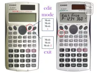
Adjusted Charge on TKMU starts when the function switch SW4 (922) on the main board of the OC only is turned ON. This can be accomplished in one of two ways. • The first method can be initiated by using OC dip switches. On the main board of the outdoor unit turn ONSW6-10 then dip switches SW4-2,4,5,8,9,10ON.
At this point 922 should be displayed on LED 1 of the outdoor main board. • Next press and hold SWP-1 for 2 seconds or longer, LED 3 will light confirming selected function. TKMU
There’s a easier way to initiate function 922 on TKMU’s, by using M-Tool! This method is much easier and allows adjusted charge to be initiated and performed from your computer.
Confirm the OC address is correct then select OC Function Setting.
Put all indoor units in Test Run and Cool Mode. This will allow the indoors units to operate for a two hour period. The set point does not require changing, as it will be ignored during Test Run.
Be sure the Ctrl Mode of the outdoor unit or units is Ordinary. • Be sure it has been at least 30 minutes since system startup.
Here we can confirm that the Ctrl Mode is in Ordinary and all indoor units are in Test Run Cool Mode.
Is discharge gas temperature TH4 less than 212 ºF? • If not then gradually add liquid refrigerant to the low pressure service port until TH4 is less than 212 ºF.
Remember discharge gas temperature on TGMU generation is TH11. All others THMU, TJMU and TKMU discharge gas temperature is TH4.
TH4 must be less than 212 ºF before continuing. • After adding refrigerant wait at least 5 minutes to allow system to adjust. Weight the charge and record the amount!
Once TH4 is less than 212 ºF be sure the compressor frequencies of the OC and OS are stable before continuing to the next step.
“Stable frequency,” means there will be no hunting. The frequencies will lock into a specific range.
Is the superheat (SH) equal to or greater than 9 ºF? • If no be sure the position of the LEV’s are stable. • The SH of all indoor units should be between 9 ºF and 27 ºF before continuing to the next step.
The pulse position of the LEV’s (Li) will stabilize and SH should be between 9 ºF and 27 ºF. Remember if there is a malfunctioning LEV causing a indoor unit to flood, SH will be low and system data may mimic low charge!
SC1 is the sub cooling of the first heat exchanger in the BC. It should be between 9 ºF and 27 ºF. • If not, gradually add liquid refrigerant to the low pressure service port.
Remember to allow at least 5 minutes for the system to adjust after adding refrigerant. This will help ensure you do not overcharge!
SC6 is the sub cooling on the second heat exchanger in the BC. It should be 27 ºF or greater. • If not, gradually add liquid refrigerant to the low pressure service port.
Is discharge gas temperature TH4 on the OC and OS below 203 ºF? • If not gradually add refrigerant until TH4 is less than 203 ºF. • If yes then adjusted charge is complete.
Turn off dip switches that initiated Refrigerant Amount Adjust Mode. • If you used M-Tool to start function 922 it will be necessary to Stop indoor unit operation before turning off 922 via M-Tool.
Cooling only mode is uses for adjusting charge because there is a specific amount of sub cooling required on the two tube in tube heat exchangers in the Branch Controller (BC). The nomenclature identifying temperature sensors and sub cooling will change from manuals to M-Tool. TH11 = TH1 SC11 = SC1 TH12 = TH2 SC16 = SC6 TH15 = TH5 TH16 = TH6
Sub cooling on the first tube in tube heat exchanger (SC1) is calculated using PS1 (pressure sensor) and TH11 (temperature sensor).
Sub cooling on the second tube in tube heat exchanger (SC6) is calculated using PS3 (pressure sensor)and TH16 (temperature sensor).
The heat exchanger superheat (SH2) is calculated using temperature sensors TH15 and TH12.