Download
1 / 10
120 likes | 251 Vues
This comprehensive overview explores the principles of AC and DC motors, including their generation, operation, and the fundamental role of magnetism and electricity. Key concepts such as synchronous and induction motors, alongside stepper motors and gear ratios, are explained in detail. The historical context highlights the War of Currents with innovators like Tesla and Edison shaping modern power distribution. Learn about how these motors convert mechanical energy into electrical energy and vice versa, crucial for modern robotics and intelligent agents.

E N D
AC/DC, Stepper Motors and Gearing CSC 338 – Robotics and Intelligent Agents Theodore Trotz
Magnetism Electricity • The link between magnetism and electricity was first discovered during an experiment • Hans Christian Ørsted discovered that a compass needle deflected from true north when electric current flowing through a wire was switched on and off • Expanded on by Albert Einstein in 1905 with his theory of Special Relativity • Connects Electricity and Magnetism
War of Currents • Alternating Current – Direction between load and generator reverses cyclically • Promoted in late 1800s by Nikola Tesla and George Westinghouse • Direct Current – Direction between load and generator is constant in direction • Promoted by Thomas Edison • AC eventually won as the better way to distribute power. • AC cables could transmit much further than DC • AC cables were smaller as well
Generators and Motors • All contemporary Power Plants work essentially the same way • Mechanical energy is converted into electrical energy • A coil of wire is spun inside a magnetic field exciting the electrons • The reverse conversion is done by an electric motor
AC Motors • Two Main Types of AC Motors • Synchronous – Rotates at exactly the supply frequency or submultiples of that frequency • Induction – Rotates slightly slower than the supply frequency
Synchronous Motors • Power Plants use synchronous generators • It’s important to keep the supply frequency constant • Used where high precision is required • Seen in Stepper Motors • Clocks also employ synchronous motors
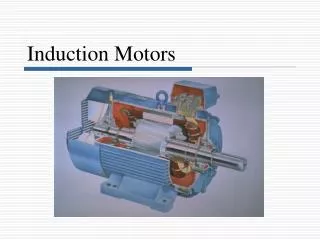
Induction Motors • Induction motors use a time varying magnetic field to move the rotor • The rotor is carried around the magnetic field, but at a slightly slower rate • Induction motors are also known as asynchronous motors • The difference between the rotors output and the magnetic field is called slip which increases with load • Induction motors often use a squirrel cage design • http://www.youtube.com/watch?v=PYesQZ20Kwc
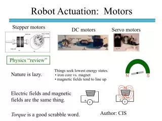
DC Motors • Two Main Types of DC Motors • Brushed • Brushless • Brushed Motors have two brushes which physically contact rotors split ring • This ring supplies the charge onto the rotors coil, which is typically suspended between permanent magnets • Brushless Motors require a motor controller to convert DC to AC • The design is essentially the opposite of a brushed motor; permanent magnet on the inside and a varying electromagnetic field stator.
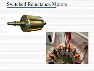
Stepper Motors • A brushless, synchronous motor that can divide a full rotation into a large number of steps • Require motor controller or drive circuits • Consist of multiple toothed electromagnets around a central gear-shaped piece of iron • Can be viewed as a synchronous AC motor with the number of stators increased
Gear Ratios • It may be necessary to increase or reduce the speed at which the output shaft turns. For that we need to understand gear ratios • This is easy if we understand the circumference of a circle C = 2 * pi * R • If two gears are meshed together, one with twice the circumference, it will yield a 2:1 ratio • Teeth are put on gears for precision and to prevent slippage • To determine the ratio, count the number of teeth on each gear and divide • Consider one gear with 60 teeth and another with 20. 60/20 = 3 which produces a 3:1 ratio