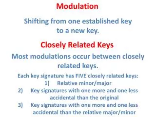
Noise in Modulation
Noise in Modulation. The primary figure of merit for signals in analog systems is signal-to-noise ratio . The signal-to-noise ratio is the ratio of the signal power to the noise power.

Noise in Modulation
E N D
Presentation Transcript
The primary figure of merit for signals in analog systems is signal-to-noise ratio. The signal-to-noise ratio is the ratio of the signal power to the noise power. While the amount of external ambient noise is not always within the control of a communications engineer, the way in which we can distinguish between the signal an the noise is. The demodulation process for any modulation system seeks to recreate the original modulating signal with as little attenuation of the signal and as much attenuation of the noise as possible.
The signal-to-noise ratio changes as the modulated signal goes through the demodulation process. We wish the signal-to-noise ratio to increase as a result of the demodulation process. The extent to which the signal-to-noise ratio increases is called the signal-to-noise improvement, or SNRI. This signal-to-noise improvement is equal to the ratio of the demodulated signal-to-noise ratio to the input signal-to-noise ratio.
The calculation of the signal-to-noise improvement (SNRI) is shown in the following diagram. so(t) si(t) Demodulator ni(t) no(t)
In determining the ability of a demodulator to discriminate signal from noise, we calculate Psi, Pso, Pni and Pno and plug these values (or expressions) into the expression
Noise in Amplitude Modulated Systems • The SNRI will be calculated for DSB-SC and DSB-LC. • A DSB-SC demodulator is linear: the signal and the noise components can be considered separately. • A DSB-LC demodulator is non-linear: the signal and the noise components cannot be treated separately.
The expression for the modulated carrier for DSB-SC is Demodulation of this signal is performed by multiplying xc(t) by cos wct and low-pass filtering the result. d(t) LPF X si(t) = xc(t) so(t) coswct
The result of this demodulation can be seen by analysis: Low-pass filtering the result eliminates the cos 2wct component.
Based upon these relationships, we can find the ratio of the signal input power and the signal output power.
The other half of the calculation deals with the noise. Let us use the quadrature decomposition to represent the noise: It is this signal which will represent ni(t).
The noise input to the demodulator (in the above form) is demodulated along with the signal. Because the demodulator is linear, we can treat the noise separately from the signal. ni(t) = nccoswct – nssinwct dn(t) LPF X no(t) coswct
After dn(t) passes through the low-pass filter, all we have left is
The ratio of the noise powers becomes Finally, our signal-to-noise improvement becomes
Thus, the DSB-SC demodulation process improvesthe signal-to-noise ratio by a factor of two.
The expression for the modulated carrier for DSB-LC is (This is a simplified version of the more accurate expression which takes into account the modulation index. In this simplified version, the modulation index is equal to one.) The demodulation process extracts m(t) from xc(t).
The modulating signal m(t) is assumed here to have zero mean. If m(t) = coswmt, then
The output power is simply which is equal to ½ if m(t) = coswmt. Thus, when m(t) is a sinewave, our signal power ratio is
Now, we deal with the noise. As mentioned previously, since the demodulation process is non-linear, we cannot treat the signal and the noise separately. To deal with the noise, we retain the carrier, but set the modulating signal to zero. Thus, the signal that we demodulate is
The resultant output from demodulating this signal will be the output noise power. To demodulate this signal (analytically), we use the quadrature decomposition for n(t). The input to our demodulator becomes
We then work with this expression: At this point we make an assumption (which turns out to be quite reasonable in many cases):
In words, the noise (either the in-phase or quadrature component) is much smaller in magnitude that that of the signal coswct. With this assumption the input to the demodulator becomes
We recall that when the input is applied, the output is
Similarly, when the input is is applied, the output is
Thus, the noise output is The output noise power is
Thus, and
We see that the signal-to-noise improvement for DSB-LC is not as good as that of DSB-SC. The reason for using DSB-LC is that it is relatively easy to demodulate. (Standard broadcast AM [530-1640 kHz], uses DSB-LC.)
Noise in Frequency Modulated Systems • The frequency modulation and demodulation process is non-linear. • As with DSB-LC, we cannot treat the signal and the noise separately.
The expression for the modulated carrier for FM As with DSB-LC AM, he demodulation process extracts m(t) from xc(t). This extraction process consists of three steps:
Extract argument from cos(). • Subtract wct. • Differentiate what is left to get kfm(t). Based upon these three steps we can quickly get the input signal power and the output signal power.
Without much loss of generality, we can assume that m(t) = coswmt.
As with the DSB-LC AM, the effective noise input comes along with an unmodulated carrier: If use the quadrature decomposition of the noise, we have, as the effective noise input
or, This expression can be combined into a single sinewave
where At this point we make a simliar assumption to what we made with DSB-LC AM:
(The new part is the 1.) Using this assumption we have (This last is true because tan-1 x x for small values of x.)
With the assumptions given, our effective noise input becomes We may now apply our three demodulation steps: • Extract argument from cos(). • Subtract wct. • Differentiate what is left to get kfm(t).
1. 2. 3.
Thus, the output noise is All that remains to be done is to find the noise power from the noise signals [ni(t) and no(t)]. The noise power will be found from the power spectral densities of the input noise and the output noise.
The input noise is additive white Gaussian noise. The power spectral density of the input noise is The output noise is the derivative of the quadrature component of the (input) noise [ns(t)].
We know, from a previous exercise, that We need to find the power spectral density of the derivative of the quadrature component. To find this we multiply Sns(f) by the square of the transfer function for the differentiation operation.
The effect of the differentiation operation is shown in three ways: d dt . ns(t) ns(t) j2pf Ns(f) No(f) |2pf|2 Sns(f) Sno(f)
Thus, the power spectral density of the output noise is Now that we have the power spectral densities of the input and the output spectra, all that remains to find the power is to integrate the respective power spectral densities over the appropriate frequencies.
The input noise is a bandpass process. Let BT be the bandwidth. Sni(f) N0/2 f BT
The input noise is a lowpass process. Let W be the bandwidth. Sno(f)=N04p2f2 f -W W