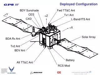
Deployed Configuration
Explore the deployed configurations and components of a spacecraft, including antennas, sunshades, solar arrays, batteries, and more in detailed isometric views, showing thermal plumes, access holes, and thruster separation planes.

Deployed Configuration
E N D
Presentation Transcript
Deployed Configuration Fwd TT&C Ant BDY Sunshade +Y CES Tx1 Ant +Z CXD L-Band/ITS Ant +X Solar Array BDA Rx Ant Tx2 Ant BDV Ant Battery Aft TT&C Ant RCS Mod
Deployed Configuration BDV Antenna (Deployed)
Deployed Y Side View BDA Rx Ant (Deployed) Centerline of Solar Array Centerline of BDV Ant & RCS Thrusters Separation Plane (SEP) (Z=0.0)
Stowed Isometric View Thermal Plume (1 Sun)
Forward Bulkhead CXD BDY Sunshade CES BDY Access Hole +Y Tx2 Ant Tx1 Ant +X -X BDV Ant NAV/ITS Ant Fwd TT&C Ant -Y BDA Rx Ant Fairing Envelope
Side View Fwd TT&C Ant (Conical & Bicone) BDA Rx Ant BDY Sunshade NAV/ITS Ant RCS Thruster Mod (2) -X +X Aft TT&C Ant
Aft Bulkhead Battery Mod (4) -Y Thermal blanket (trough) Battery/Umb Connector Panel (2) Direction of Vent flow (3) BDV Ant +X -X Test Connector Panel (2) Aft TT&C Ant (Direction of flow) Umbilical (2) To PLA +Y Fairing Envelope