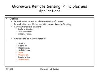
Active and Passive Microwave Remote Sensing
Active and Passive Microwave Remote Sensing . Lecture 7 Oct 6, 2004. Reading materials: Chapter 9. Basics of passive and active RS. Passive : uses natural energy, either reflected sunlight (solar energy) or emitted thermal or microwave radiation. Active : sensor creates its own energy


Active and Passive Microwave Remote Sensing
E N D
Presentation Transcript
Active and Passive Microwave Remote Sensing Lecture 7 Oct 6, 2004 Reading materials: Chapter 9
Basics of passive and active RS • Passive: uses natural energy, either reflected sunlight (solar energy) or emitted thermal or microwave radiation. • Active: sensor creates its own energy • Transmitted toward Earth or other targets • Interacts with atmosphere and/or surface • Reflects back toward sensor (backscatter)
Widely used active RS systems Active microwave (RADAR: RAdio Detection And Ranging, read p285 for an explanation) Long-wavelength microwaves (1 – 100 cm) LIDAR (LIght Detection And Ranging) Short-wavelength laser light (UV, visible, near IR) SONAR (SOund Navigation And Ranging) Sound waves through a water column. Sound waves extremely slow (300 m/s in air, 1,530 m/s in sea-water) Bathymetric sonar (measure water depths and, hence changes in bottom topography ) Imaging sonar or sidescan imaging sonar (imaging the bottom topography and bottom roughness) It is not our focus in this remote sensing class.
Microwaves Band Designations (common wavelengths Wavelength () Frequency () shown in parentheses)in cm in GHz _______________________________________________ Ka (0.86 cm) 0.75 - 1.18 40.0 to 26.5 K 1.18 - 1.67 26.5 to 18.0 Ku 1.67 - 2.4 18.0 to 12.5 X (3.0 and 3.2 cm) 2.4 - 3.8 12.5 - 8.0 C (7.5, 6.0 cm) 3.8 - 7.5 8.0 - 4.0 S (8.0, 9.6, 12.6 cm) 7.5 - 15.0 4.0 - 2.0 L (23.5, 24.0, 25.0 cm) 15.0 - 30.0 2.0 - 1.0 P (68.0 cm) 30.0 - 100 1.0 - 0.3
Two active radar imaging systems In world war II, ground based radar was used to detect incoming planes and ships. Imaging RADAR was not developed until the 1950s (after the world war II). Since then, the side-looking airborne radar (SLAR) has been used to get detail image of enemy sites along the edge of the fight field. • Real aperture radar • Aperture means antenna • A fixed length (for example: 1 - 11m) • Synthetic aperture radar (SAR) • 1m (11m) antenna can be synthesized electronically into a 600m (15 km) synthetic length. • Most (air-, space-borne) radar systems now use SAR.
Principle of SLAR A CRT (cathode ray tube) shows a quick-look display
Radar Nomenclature • nadir • azimuth (or flight) direction • look (or range) direction • range (near, middle, and far) • depression angle () • incidence angle () • altitude above-ground-level, H • polarization
Polarization • Unpolarizedenergy vibrates in all possible directions perpendicular to the direction of travel. • The pulse of electromagnetic energy is filtered and sent out by the antenna may be vertically or horizontallypolarized. • The pulse of energy received by the antenna may be vertically or horizontallypolarized • VV, HH – like-polarized imagery • VH, HV- cross-polarized imagery
Slant-range vs. Ground-range geometry Radar imagery has a different geometry than that produced by most conventional remote sensor systems, such as cameras, multispectral scanners or area-array detectors. Therefore, one must be very careful when attempting to make radargrammetric measurements. • Uncorrected radar imagery is displayed in what is called slant-range geometry, i.e., it is based on the actual distance from the radar to each of the respective features in the scene. • It is possible to convert the slant-range display into the true ground-range display on the x-axis so that features in the scene are in their proper planimetric (x,y) position relative to one another in the final radar image.
Most radar systems and data providers now provide the data in ground-range geometry
Range (or across-track) Resolution • t.c called pulse length. It seems the short pulse length will lead fine range resolution. • However, the shorter the pulse length, the less the total amount of energy that illuminates the target. Pulse duration (t) = 0.1 x 10 -6 sec t.c/2 t.c/2
Azimuth (or along-track) Resolution • The shorter wavelength and longer antenna will improve azimuth resolution. • The shorter the wavelength, the poorer the atmospheric and vegetation penetration capability • There is practical limitation to the antenna length, while SAR will solve this problem.
A major advance in radar remote sensing has been the improvement in azimuth resolution through the development of synthetic aperture radar (SAR) systems. Great improvement in azimuth resolution could be realized if a longer antenna were used. Engineers have developed procedures to synthesize a very long antenna electronically. Like a brute force or real aperture radar, a synthetic aperture radar also uses a relatively small antenna (e.g., 1 m) that sends out a relatively broad beam perpendicular to the aircraft. The major difference is that a greater number of additional beams are sent toward the object. Doppler principles are then used to monitor the returns from all these additional microwave pulses to synthesize the azimuth resolution to become one very narrow beam. Synthetic Aperture Radar - SAR Azimuth resolution is constant = D/2, it is independent of the slant range distance, , and the platform altitude.
Penetration ability to forest Response of A Pine Forest Stand to X-, C- and L-band Microwave Energy
Penetration ability to subsurface
Roughness and Penetration ability to subsurface Railway hw90 Radar Image ETM+ Image Xie et al., 2004
Penetration ability to heavy rainfall SIR-C/X-SAR Images of a Portion of Rondonia, Brazil, Obtained on April 10, 1994
Radar Shadow • Shadows in radar images can enhance the geomorphology and texture of the terrain. Shadows can also obscure the most important features in a radar image, such as the information behind tall buildings or land use in deep valleys. If certain conditions are met, any feature protruding above the local datum can cause the incident pulse of microwave energy to reflect all of its energy on the foreslope of the object and produce a black shadow for the backslope • Unlike airphotos, where light may be scattered into the shadow area and then recorded on film, there is no information within the radar shadow area. It is black. • Two terrain features (e.g., mountains) with identical heights and fore- and backslopes may be recorded with entirely different shadows, depending upon where they are in the across-track. A feature that casts an extensive shadow in the far-range might have its backslope completely illuminated in the near-range. • Radar shadows occur only in the cross-track dimension. Therefore, the orientation of shadows in a radar image provides information about the look direction and the location of the near- and far-range
Shadows and look direction Shuttle Imaging Radar (SIR-C) Image of Maui
Radar Noise – Speckle Speckle is a grainy salt-and-pepper pattern in radar imagery present due to the coherent nature of the radar wave, which causes random constructive and destructive interference, and hence random bright and dark areas in a radar image. The speckle can be reduced by processing separate portions of an aperture and recombining these portions so that interference does not occur. This process, called multiple looks or non-coherent integration, produces a more pleasing appearance, and in some cases may aid in interpretation of the image but at a cost of degraded resolution. N (D/2) N, number of looks D, antenna length
Another way to remove speckle noise Blurred objects and boundary Statistical algorithms Geometric algorithms G-MAP Gamma Maximum A Posteriori Filter Xie et al., 2004
Striping Noise and Removal CPCA Combined Principle Component Analysis Xie et al., 2004
Major Active Radar Systems • Seasat, June 1978, 105 days mission, L-HH band, 25 m resolution • SIR-A, Nov. 1981, 2.5 days mission, L-HH band, 40 m resolution • SIR-B, Oct. 1984, 8 days mission, L-HH band, about 25 m resolution • SIR-C, April and Sept. 1994, 10 days each. X-, C-, L- bands multipolarization (HH, VV, HV, VH), 10-30 m resolution, • JERS-1, 1992-1998, L-band, 15-30 m resolution, (Japan) • RADARSAT, Jan. 1995-now, C-HH band, 10, 50, and 100 m, (Canada) • ERS-1, 2, July 1991-now, C-VV band, 20-30 m, (European) • AIRSAR/TOPSAR, 1998-now, C,L,P bands with full polarization, 10m, • NEXRAD, 1988-now, S-band, 1-4 km, • TRMM precipitation radar, 1997, Ku-band, 4km, vertical 250m, (USA and Japan)
Advantages of active radar • All weather, day or night • Some areas of Earth are persistently cloud covered • Penetrates clouds, vegetation, dry soil, dry snow • Sensitive to water content (soil moisture), roughness • Can measure waves • Sensitive to polarization • Interferometry
Principals • While dominate wavelength of Earth is 9.7 um, a continuum of energy is emitted from Earth to the atmosphere. In fact, the Earth passively emits a steady stream of microwave energy, though it is relatively weak in intensity. • A suit of radiometers developed can record it. They measure the brightness temperature of the terrain or the atmosphere. This is much like the thermal infrared radiometer for temperature. • A matrix of brightness temperature values can then be used to construct a passive microwave image.
Some important passive microwave radiometers • Special Sensor Mirowave/Imager (SSM/I) • It was onboard the Defense Meterorological Satellite Program (DMSP) since 1987 • It measure the microwave brightness temperatures of atmosphere, ocean, and terrain at 19.35, 22.23, 37, and 85.5 GHz. • TRMM microwave imager (TMI) • It is based on SSM/I, and added one more frequency of 10.7 GHz.