Download
1 / 7
70 likes | 230 Vues
AC Coupled Point to Point Data Transmission on SPI chip. Mitch and Nandor July 20, 2009. Driver and Rcvr Hookup ( Fabbed and Working in TSMC’s .25um Process). Driver. Rcvr. ….Lots of strays…. ….Different Voltages…. Rcvr with Hysteresis. Input Impedance ~ 4k ~vdd/2. H. H. INP.

E N D
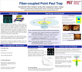
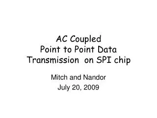
AC Coupled Point to Point Data Transmission on SPI chip Mitch and Nandor July 20, 2009
Driver and Rcvr Hookup(Fabbed and Working in TSMC’s .25um Process) Driver Rcvr ….Lots of strays…. ….Different Voltages….
Rcvr with Hysteresis Input Impedance ~ 4k ~vdd/2 H H INP INM Out H H H Hysteresis switch
SPI Driver Program Current Drive Aligns Sig and Sig_bar To minimize common mode distortion Current Driver Switches OutP OutN IN
Transient ResponseCase I Correct Initial Hysteresis Digital Input Receiver Output (matches with delay) AC inputs to Rcvr. Input settles to Hysteresis value
Transient ResponseCase II Wrong Initial Hysteresis Driver Input Pulse Exceeds Rcvr Input RC time const. Rcvr Output Correct Data NO Data Initial Hysteresis in direction of first edge AC coupled Rcvr Inputs
Notes 1)To avoid violating our NDA we will develop and distribute a receiver and driver model using LTSPICE compatible parts. 2) Notice that when the hysteresis is phased correctly with the first data edge then transmission is flawless with any combination of data. 3) Data transmission fails if the first edge of data is in the same direction as the hysteresis, But if a logic pulse of several Rcvr RC time constants is sent ( say during a beam gap) the hsyteresis phase is corrected.Note that no problem is induced by the long pulse if hysteresis is not flipped.