Download
1 / 71
750 likes | 1.23k Vues
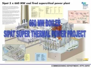
Devdeep Bose DGM ( Commng & Testing). COMMISSIONING DEPARTMENT, NTPC-SIPAT. COMMISSIONING DEPARTMENT, NTPC-SIPAT. COMMISSIONING DEPARTMENT, NTPC-SIPAT. COMMISSIONING DEPARTMENT, NTPC-SIPAT. COMMISSIONING DEPARTMENT, NTPC-SIPAT. COMMISSIONING DEPARTMENT, NTPC-SIPAT.

E N D
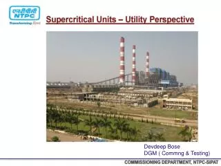
Devdeep Bose DGM ( Commng & Testing) COMMISSIONING DEPARTMENT, NTPC-SIPAT
POINTS OF DISCUSSION • SUB CRITICAL & SUPER CRITICAL BOILER • SIPAT BOILER DESIGN • SIPAT TURBINE DESIGN • DESIGN PARAMETERS • COMMISSIONING • PRE COMMISSIONING PROBLEMS • POST COMMISSIONING PROBLEM COMMISSIONING DEPARTMENT, NTPC-SIPAT
Net Plant Heat Rate = NTRH = 2207 KCal / KWHR ( at 100% TMCR) 80% TMCR = 2222 Kcal / KWHR 60% TMCR = 2276 Kcal / KWHR 50% TMCR = 2376 Kcal / KWHR Plant Efficiency at 100% TMCR = 38.96% 80% TMCR = 38.7 % 60% TMCR = 37.78% 50% TMCR = 36.19%
STEAM GENERATOR • Supplier : M/s DOOSAN • Erection By : M/s L&T COMMISSIONING DEPARTMENT, NTPC-SIPAT
UNDERSTANDING SUPER CRITICAL TECHNOLOGY • When Water is heated at constant pressure above the critical pressure, its temperature will never be constant • No distinction between the Liquid and Gas, the mass density of the two phases remain same • No Stage where the water exist as two phases and require separation : No Drum • The actual location of the transition from liquid to steam in a once through super critical boiler is free to move with different condition : Sliding Pressure Operation • For changing boiler loads and pressure, the process is able to optimize the amount of liquid and gas regions for effective heat transfer. COMMISSIONING DEPARTMENT, NTPC-SIPAT
SUPER CRITICAL BOILER CYCLE WITH SH, RH & Regeneration TEMP 3 1 568’C 540’C 600 256 Kg/cm2 500 Steam flow :2225 T/Hr Steam temp : 540 ‘c Steam Pres : 256 kg/cm2 RH pre : 51.6 Kg/cm2 RH Temp : 568’c Feed water Temp : 291’c 400 2 300 200 100 5 4 0 ENTROPY
540°C, 255 Ksc 568°C, 47 Ksc 492°C, 260 Ksc 457°C, 49 Ksc FUR ROOF I/L HDR ECO HGR O/L HDR HRH LINE MS LINE 411°C, 277Ksc 411°C, 275 Ksc SEPARATOR STORAGE TANK FINAL SH FINAL RH LTRH DIV PANELS SH PLATEN SH VERTICAL WW G ECO JUNCTION HDR LPT IPT LPT 305°C, 49 Ksc CONDENSER HPT ECONOMISER ECO I/L Spiral water walls FEEDWATER BWRP 290°C, 302 KSC FUR LOWER HDR FRS
Steam Partial Steam Generation Complete or Once-through Generation Steam Heat Input Water Heat Input Water Water Boiling process in Tubular Geometries
SIPAT SUPER CRITICAL BOILER • BOILER DESIGN PARAMETER • DRUM LESS BOILER : START-UP SYSTEM • TYPE OF TUBE • Vertical • Spiral • SPIRAL WATER WALL TUBING • Advantage • Disadvantage over Vertical water wall COMMISSIONING DEPARTMENT, NTPC-SIPAT
Vertical Tube Furnace • To provide sufficient flow per tube, constant pressure furnaces employ vertically oriented tubes. • Tubes are appropriately sized and arranged in multiple passes in the lower furnace where the burners are located and the heat input is high. • By passing the flow twice through the lower furnace periphery (two passes), the mass flow per tube can be kept high enough to ensure sufficient cooling. • In addition, the fluid is mixed between passes to reduce the upset fluid temperature. COMMISSIONING DEPARTMENT, NTPC-SIPAT
Spiral Tube Furnace • The spiral design, on the other hand, utilizes fewer tubes to obtain the desired flow per tube by wrapping them around the furnace to create the enclosure. • This also has the benefit of passing all tubes through all heat zones to maintain a nearly even fluid temperature at the outlet of the lower portion of the furnace. • Because the tubes are “wrapped” around the furnace to form the enclosure, fabrication and erection are considerably more complicated and costly. COMMISSIONING DEPARTMENT, NTPC-SIPAT
SPIRAL WATER WALL • ADVANTAGE • Benefits from averaging of heat absorption variation : Less tube leakages • Simplified inlet header arrangement • Use of smooth bore tubing • No individual tube orifice • Reduced Number of evaporator wall tubes & Ensures minimum water flow • Minimizes Peak Tube Metal Temperature • Minimizes Tube to Tube Metal Temperature difference • DISADVANTAGE • Complex wind-box opening • Complex water wall support system • tube leakage identification : a tough task • More the water wall pressure drop : increases Boiler Feed Pump Power • Adherence of Ash on the shelf of tube fin
BOILER OPERATING PARAMETER COMMISSIONING DEPARTMENT, NTPC-SIPAT COMMISSIONING DEPARTMENT, NTPC-SIPAT
Coal Analysis • High erosion potential for pulverizer and backpass tube is expected due to high ash content. • 2. Combustibility Index is relatively low but combustion characteristic is good owing to high volatile content. COMMISSIONING DEPARTMENT, NTPC-SIPAT COMMISSIONING DEPARTMENT, NTPC-SIPAT
Ash Analysis • Lower slagging potential is expected due to low ash fusion temp. and low basic / acid ratio. • 2. Lower fouling potential is expected due to low Na2O and CaO content.
BOILER LOAD CONDITION • Constant Pressure Control • Above 90% TMCR The MS Pressure remains constant at rated pressure • The Load is controlled by throttling the steam flow • Below 30% TMCR the MS Pressure remains constant at minimum Pressure • Sliding Pressure Control • Boiler Operate at Sliding pressure between 30% and 90% TMCR • The Steam Pressure And Flow rate is controlled by the load directly COMMISSIONING DEPARTMENT, NTPC-SIPAT COMMISSIONING DEPARTMENT, NTPC-SIPAT
Boiler Load % 60 80 100 40 20 +1 0 -1 Efficiency Change % -2 -3 -4 CONSTANT PRESSURE Vs VARIABLE PRESSURE BOILER CHARACTERSTIC Variable Pressure Constant Pressure COMMISSIONING DEPARTMENT, NTPC-SIPAT
Benefits Of Sliding Pressure Operation ( S.P.O) • Able to maintain constant first stage turbine temperature • Reducing the thermal stresses on the component : Low Maintenance & Higher Availability • No additional pressure loss between boiler and turbine. • low Boiler Pr. at low loads. WHY NOT S.P.O. IN NATURAL/CONTROL CIRCULATION BOILERS • Circulation Problem : instabilities in circulation system due to steam formation in down comers. • Drum Level Control : water surface in drum disturbed. • Drum : (most critical thick walled component) under highest thermal stresses COMMISSIONING DEPARTMENT, NTPC-SIPAT
STEAM TURBINE K-660-247 • LMZ (LENINGRADSKY METALLICHESKY ZAVOD) • K STANDS FOR KLAPAN LTD.,BULGARIA WHICH SUPPLIES TURBINE,NOZZLES,DIAPHRAGMS, SEALS,BLADES ETC. COMMISSIONING DEPARTMENT, NTPC-SIPAT
1.TG DECK IS VIS SUPPORTED AND HAS 26 CONCRETE COLUMNS (T1 – T26). 2.TG HALL IS CONSTITUTED OF 3 MAINS ROWS OF COLUMNS – A,B ,C ROW AND TWO BAYS – AB BAY AND BC BAY. THE WIDTH OF AB BAY IS 36m AND BC BAY IS 12m 3.CONDENSER TUBE BANKS (CW PATH) HAS AN INCLINATION OF 40. 4.THERE ARE TWO MAIN EOT CRANES FOR TG HALL.EACH EOT CRANE IS HAVING A CAPACITY OF 200t FOR MAIN HOIST AND 20t FOR AUXILIARY HOIST. 35.5m IS THE MAXIMUM VERTCAL DISTANCE A HOIST CAN TRAVEL.TANDEM OPERATION OF TWO EOT CRANES ARE ALLOWED. COMMISSIONING DEPARTMENT, NTPC-SIPAT
Condenser • Design LMZ • Design CW Flow 64000 m3/hr • Vacuum 77 mm Hg (abs) at 33 0C • 89 mm Hg (abs) at 36 0C • No. of passes 1 • Total no. of tubes 22.225 (OD)x0.71 (t) - 29920 • 22.225 (OD)x1.00 (t) - 2080 • Tube material ASTM A-249 TP 304 • Rated TTD 3.40C • DT of CW 100C COMMISSIONING DEPARTMENT, NTPC-SIPAT
Condensate Extraction Pump • Design flow rate 238.75 Kg/s • Discharge pressure 32.15 Ksc • Shut off head 395 m • Pump speed 1480 rpm • Power input 972.3 KW • No. of stages 6 • Type of first stage impeller double entry • Depth 7.43 m COMMISSIONING DEPARTMENT, NTPC-SIPAT
MDBFP • Pump flow 769.950 TPH • Suction temp 186.2 0C • BP Suction pr. 14.05 ata • BFP Suction pr. 21.01 ata • BFP Discharge pr. 335.78 ata • BFP Discharge temp. 187.9 0C • BP Discharge pr. 22.01 ata • Shut off head 4830 m • BFP Speed 6275 rpm • BP Speed 1490 rpm • Normal R/C flow 220 TPH • HC Rated O/P Speed 6505 rpm • Outer casing type barrel • No. of stages 7 • BFP warm up flow 15 TPH COMMISSIONING DEPARTMENT, NTPC-SIPAT
TDBFP • Pump flow 1283.14 TPH • Suction temp 186.2 0C • BP Suction pr. 14.10 ata • BFP Suction pr. 28.24 ata • BFP Discharge pr. 335.83 ata • BFP Discharge temp. 187.8 0C • BP Discharge pr. 29.06 ata • Shut off head 4580 m • BFP Speed 4678 rpm • BP Speed 2098 rpm • Normal R/C flow 365 TPH • HC Rated O/P Speed 6505 rpm • Outer casing type barrel • No. of stages 7 • BFP warm up flow 20 TPH COMMISSIONING DEPARTMENT, NTPC-SIPAT
Drip Pump • Design flow rate 324.509 TPH • Discharge pressure 43 ata • Shut off head 306.7 m • Pump speed 1486 rpm • Power input 310.1 KW • No. of stages 5 • Type of first stage impeller centrifugal, single entry • Depth 1090 mm COMMISSIONING DEPARTMENT, NTPC-SIPAT