Download
1 / 88
1.01k likes | 1.79k Vues
660 MW BOILER SIPAT SUPER THERMAL POWER PROJECT. COMMISSIONING DEPARTMENT, NTPC-SIPAT. POINTS OF DISCUSSION SUB CRITICAL & SUPER CRITICAL BOILER SIPAT BOILER DESIGN BOILER DESIGN PARAMETERS CHEMICAL TREATMENT SYSTEM OPERATION FEED WATER SYSTEM BOILER CONTROL BOILER LIGHT UP

E N D
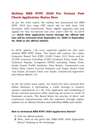
660 MW BOILER SIPAT SUPER THERMAL POWER PROJECT COMMISSIONING DEPARTMENT, NTPC-SIPAT
POINTS OF DISCUSSION • SUB CRITICAL & SUPER CRITICAL BOILER • SIPAT BOILER DESIGN • BOILER DESIGN PARAMETERS • CHEMICAL TREATMENT SYSTEM • OPERATION • FEED WATER SYSTEM • BOILER CONTROL • BOILER LIGHT UP • START UP CURVES COMMISSIONING DEPARTMENT, NTPC-SIPAT
WHY SUPER CRITICAL TECHNOLOGY • To Reduce emission for each Kwh of electricity generated : Superior Environmental 1% rise in efficiency reduce the CO2 emission by 2-3% • The Most Economical way to enhance efficiency • To Achieve Fuel cost saving : Economical • Operating Flexibility • Reduces the Boiler size / MW • To Reduce Start-Up Time COMMISSIONING DEPARTMENT, NTPC-SIPAT
UNDERSTANDING SUB CRITICAL TECHNOLOGY • Water when heated to sub critical pressure, Temperature increases until it starts boiling • This temperature remain constant till all the water converted to steam • When all liquid converted to steam than again temperature starts rising. • Sub critical boiler typically have a mean ( Boiler Drum) to separate Steam And Water • The mass of this boiler drum, which limits the rate at which the sub critical boiler responds to the load changes • Too great a firing rate will result in high thermal stresses in the boiler drum COMMISSIONING DEPARTMENT, NTPC-SIPAT
Role of SG in Rankine Cycle Perform Using Natural resources of energy …….
UNDERSTANDING SUPER CRITICAL TECHNOLOGY • When Water is heated at constant pressure above the critical pressure, its temperature will never be constant • No distinction between the Liquid and Gas, the mass density of the two phases remain same • No Stage where the water exist as two phases and require separation : No Drum • The actual location of the transition from liquid to steam in a once through super critical boiler is free to move with different condition : Sliding Pressure Operation • For changing boiler loads and pressure, the process is able to optimize the amount of liquid and gas regions for effective heat transfer. COMMISSIONING DEPARTMENT, NTPC-SIPAT
Circulation Vs Once Through COMMISSIONING DEPARTMENT, NTPC-SIPAT
No Religious Attitude COMMISSIONING DEPARTMENT, NTPC-SIPAT
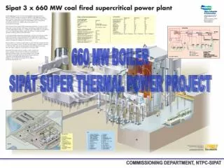
540°C, 255 Ksc 568°C, 47 Ksc 492°C, 260 Ksc 457°C, 49 Ksc FUR ROOF I/L HDR ECO HGR O/L HDR HRH LINE MS LINE 411°C, 277Ksc 411°C, 275 Ksc SEPARATOR STORAGE TANK FINAL SH FINAL RH LTRH DIV PANELS SH PLATEN SH VERTICAL WW G ECO JUNCTION HDR LPT IPT LPT 305°C, 49 Ksc CONDENSER HPT ECONOMISER ECO I/L Spiral water walls FEEDWATER BWRP 290°C, 302 KSC FUR LOWER HDR FRS
Steam Partial Steam Generation Complete or Once-through Generation Steam Heat Input Water Heat Input Water Water Boiling process in Tubular Geometries
SEPARATOR TANK COMMISSIONING DEPARTMENT, NTPC-SIPAT
PENTHOUSE Eco. O/L hdr (E7) LTRH O/L hdr (R8) 2nd pass top hdrs (S11) Back pass Roof o/l hdr (S5) SH final I/L hdr (S34) SH final O/L hdr (S36) F19 1st pass top hdrs RH O/L hdr (R12) RH I/L hdr (R10) Platen O/L hdr (S30) F28 Platen I/L hdr (S28) F28 Div. Pan. O/L hdrs (S24) Div. Pan. I/L hdrs (S20) 1st pass top hdrs F8 Back pass Roof i/l hdr S2 Separator (F31) Storage Tank (F33)
SIPAT SUPER CRITICAL BOILER • BOILER DESIGN PARAMETER • DRUM LESS BOILER : START-UP SYSTEM • TYPE OF TUBE • Vertical • Spiral • SPIRAL WATER WALL TUBING • Advantage • Disadvantage over Vertical water wall COMMISSIONING DEPARTMENT, NTPC-SIPAT
Vertical Tube Furnace • To provide sufficient flow per tube, constant pressure furnaces employ vertically oriented tubes. • Tubes are appropriately sized and arranged in multiple passes in the lower furnace where the burners are located and the heat input is high. • By passing the flow twice through the lower furnace periphery (two passes), the mass flow per tube can be kept high enough to ensure sufficient cooling. • In addition, the fluid is mixed between passes to reduce the upset fluid temperature. COMMISSIONING DEPARTMENT, NTPC-SIPAT
Spiral Tube Furnace • The spiral design, on the other hand, utilizes fewer tubes to obtain the desired flow per tube by wrapping them around the furnace to create the enclosure. • This also has the benefit of passing all tubes through all heat zones to maintain a nearly even fluid temperature at the outlet of the lower portion of the furnace. • Because the tubes are “wrapped” around the furnace to form the enclosure, fabrication and erection are considerably more complicated and costly. COMMISSIONING DEPARTMENT, NTPC-SIPAT
SPIRAL WATER WALL • ADVANTAGE • Benefits from averaging of heat absorption variation : Less tube leakages • Simplified inlet header arrangement • Use of smooth bore tubing • No individual tube orifice • Reduced Number of evaporator wall tubes & Ensures minimum water flow • Minimizes Peak Tube Metal Temperature • Minimizes Tube to Tube Metal Temperature difference • DISADVANTAGE • Complex wind-box opening • Complex water wall support system • tube leakage identification : a tough task • More the water wall pressure drop : increases Boiler Feed Pump Power • Adherence of Ash on the shelf of tube fin
BOILER OPERATING PARAMETER COMMISSIONING DEPARTMENT, NTPC-SIPAT COMMISSIONING DEPARTMENT, NTPC-SIPAT
Coal Analysis • High erosion potential for pulverizer and backpass tube is expected due to high ash content. • 2. Combustibility Index is relatively low but combustion characteristic is good owing to high volatile content. COMMISSIONING DEPARTMENT, NTPC-SIPAT
Ash Analysis • Lower slagging potential is expected due to low ash fusion temp. and low basic / acid ratio. • 2. Lower fouling potential is expected due to low Na2O and CaO content.
AIR AND FLUE GAS SYSTEM AIR PATH : Similar as 500 MW Unit FLUE GAS PATH : No Of ESP Passes : 6 Pass No Of Fields / Pass : 18 No Of Hopper / Pass : 36 Flue Gas Flow / Pass : 1058 T/ Hr 1-7 fields 70 KV. 8&9 field 90 KV COMMISSIONING DEPARTMENT, NTPC-SIPAT
M M M M M M M M M M M M M M M M M M M M M M M M M AIR MOTOR AIR MOTOR AIR MOTOR AIR MOTOR M M M M M TO PULVERISER SYSTEM HOT PRIMARY AIR DUCT PAPH # A PA FAN # A M SAPH # A FD FAN # A SAPH # B M FD FAN # B PAPH # B HOT PRIMARY AIR DUCT TO PULVERISER SYSTEM PA FAN # B LHS WIND BOX FURNACE BACK PASS ECONOMISER FINAL REHEATER LTRH PLATEN COILS FINAL SUPERHEATER DIVISIONAL PANEL RHS WIND BOX AIR PATH COMMISSIONING DEPARTMENT, NTPC-SIPAT
FUEL OIL SYSTEM Type Of Oil : LDO / HFO Boiler Load Attainable With All Oil Burner In Service : 30 % Oil Consumption / Burner : 2123 Kg / Hr Capacity Of HFO / Coal : 42.1 % Capacity Of LDO / Coal : 52.5 % HFO Temperature : 192 C All Data Are At 30 % BMCR COMMISSIONING DEPARTMENT, NTPC-SIPAT
DESIGN BASIS FOR SAFETY VALVES : • Minimum Discharge Capacities. • Safety valves on Separator and SH Combined capacity 105%BMCR • (excluding power operated impulse safety valve) • Safety valves on RH system Combined capacity 105% of Reheat • flow at BMCR • (excluding power operated impulse safety valve) • Power operated impulse safety valve 40%BMCR at super-heater outlet • 60% of Reheat flow at BMCR at RH outlet • 2. Blow down 4% (max.)b COMMISSIONING DEPARTMENT, NTPC-SIPAT
BOILER FILL WATER REQUIREMENT COMMISSIONING DEPARTMENT, NTPC-SIPAT
OXYGENATED TREATMENT OF FEED WATER “WATER CHEMISTRY CONTROL MAINTAINS PLANT HEALTH.” • Dosing of oxygen(O2) or Hydrogen peroxide (H2O2) in to feed water system. • Concentration in the range of 50 to 300 µg/L. • Formation of a thin, tightly adherent ferric oxide (FeOOH) hydrate layer. • This layer is much more dense and tight than that of Magnetite layer. 39
All Volatile Treatment Oxygenated Water Treatment 40
U # 1 FUR ROOF I/L HDR VENT HDR VENT HDR WATER LINE N2 FILL LINE N2 FILLING LINE N2 FILL LINE VENT LINE SAMPLE COOLER SAMPLE COOLER DRAIN LINE SEPRATOR #1 SEPRATOR #2 SAMPLE COOLER LINE 1 2 1 2 1 2 1 2 VENT HDR VENT HDR FUR WW HDR FUR INTERMITTENT HDR STORAGE TANK DRAIN HDR FUR BOTTOM RING HDR FLASH TANK DRAIN HDR MIXING PIECE WR ZR VENT HDR BACK PASS ECO O/L HDR N2 FILL LINE BRP ECO MIXING LINK ECO JUNCTION HDR BACK PASS ECO I/L HDR BLR FILL PUMP FROM FEED WATER TO DRAIN HDR WATER CIRCULATION SYSTEM
FEED WATER SYSTEM • MODES OF OPERATION • BOILER FILLING • CLEAN UP CYCLE • WET MODE OPERATION (LOAD < 30 % ) • DRY MODE OPERATION (LOAD > 30 %) • DRY TO WET MODE OPERATION ( WHEN START UP SYSTEM NOT AVAILABLE) COMMISSIONING DEPARTMENT, NTPC-SIPAT
BOILER FILLING LOGIC • If the water system of the boiler is empty (economizer, furnace walls, separators), then the system is filled with approximately 10% TMCR ( 223 T/Hr) feed water flow. • When the level in the separator reaches set-point, the WR valve will begin to open. • When the WR valve reaches >30% open for approximately one minute, then increase feed water flow set-point to 30% TMCR ( approx 660 T/Hr). • As the flow increases, WR valve will reach full open and ZR valve will begin to open. • The water system is considered full when: • The separator water level remains stable for two(2) minutes and • The WR valve is fully opened and ZR valve is >15% open for two(2) minutes After completion of Filling, the feed water flow is again adjusted to 10 % TMCR for Clean up cycle operation COMMISSIONING DEPARTMENT, NTPC-SIPAT
BOILER INITIAL WATER LEVEL CONTROL (UG VALVE) • The boiler circulating pump is started following the start of a feed water pump and the final clean-up cycle. • This pump circulates feed water from the evaporator outlet back to the economizer inlet. • Located at the outlet of this pump is the UG valve which controls economizer inlet flow during the start-up phase of operation. • Demand for this recirculation, control valve is established based on measured economizer inlet flow compared to a minimum boiler flow set point. COMMISSIONING DEPARTMENT, NTPC-SIPAT
Boiler Clean-up • When the feedwater quality at the outlet of deaerator and separator is not within the specified limits, a feedwater clean-up recirculation via the boiler is necessary. • During this time, constant feedwater flow of 10% TMCR ( 223 T/Hr) or more is maintained. • Water flows through the economizer and evaporator, and discharges the boiler through the WR valve to the flash tank and via connecting pipe to the condenser. • From the condenser, the water flows through the condensate polishing plant, which is in service to remove impurities ( Like Iron & its Oxide, Silica, Sodium and its salts ), then returns to the feed water tank. • The recirculation is continued until the water quality is within the specified limits. COMMISSIONING DEPARTMENT, NTPC-SIPAT