NTPC: Leading Power Company in India
NTPC, India's largest power company, with 34,854 MW generating capacity, aims to reach 75,000 MW by 2017. Learn about its coal-to-electricity process, Rankine Cycle, and Coal Handling Plant operations. Find out about Badarpur thermal power plant and Boiler Maintenance Department activities.


NTPC: Leading Power Company in India
E N D
Presentation Transcript
About NTPC NTPC, India's largest power company, was set up in 1975 to accelerate power development in India. It is emerging as an' Integrated Power Major’, with a significant presence in the entire value chain of power generation business. With a current generating capacity of 34,854 MW, NTPC has embarked on plans to become a 75,000 MW company by 2017. Presently, NTPC generates power from Coal and Gas. With an installed capacity of 34,854 MW, NTPC is the largest power generating major in the country.
NTPC BADARPUR • Badarpur thermal power plant started working with a single 95 MW unit. There were two more units installed in next two consecutive years. Now it has total 5 units with total capacity of 720 MW.
Coal to electricity The basic steps in generation of electricity from coal is carried out in three stages: • Coal to steam • Steam to mechanical power • Mechanical power to electrical power
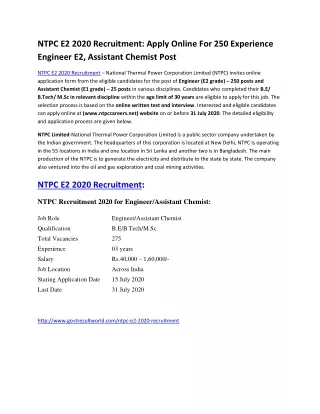
RANKINE CYCLE Rankine cycle is a basic thermodynamic cycle that converts heat into work. Rankine cycle describes a model of operation of steam heat engines most commonly found in power generation plants.
T-s diagram of a Rankine cycle operating between pressures 0-06 bar and 50 bar. there are 4 stages in rankine cycle each changing the state of fluid. • Process 1-2: The working fluid is pumped from low pressure to high pressure, as the fluid is in liquid state at this stage it requires more input. • Process 2-3:The high pressure liquid enters the boiler where it is heated at constant pressure by an external heat source to become a dry saturated vapor. • Process 3-4:The dry saturated vapor expands through a turbine, generating power. This decreases the temperature and pressure of the vapor, and some condensation may occur • Process 4-1: The wet vapor then enters a condenser where it is condensed at a constant pressure and temperature to become a saturated liquid. In an ideal Rankine cycle the pump and turbine would be isentropic i.e. the pump and turbine would generate no entropy and hence maximize the net work output.
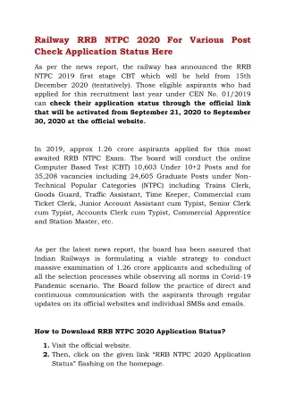
Coal Handling Plant • This plant transfers the coal to the boiler and also stores the coal in the bunker. • Wagon tipplers are employed to unload the coal wagons into coal hopper. • Vibrating screen are used for controlled removal of coal from coal hopper. • We receive coal in the form of odd lumps. These lumps are to be crushed to required sizes which is done by the coal crusher. • Electromagnetic separator performs the function of separation of iron and magnetic impurities from the coal.
Coal wagons containing coal Wagon tippler
There are three operational cycles working in CHP: • Normal Bunkering Cycle: Shifting of the coal received from coal wagons directly to coal bunkers • Coal stacking: when there is no requirement of coal in the coal bunker even then CHP has to unload the received coal which is stacked at open ground called yard. • Coal reclaiming: as and when coal wagons are not available, the requirement of the coal bunker is fulfilled from the stacked coal. this is called reclaiming cycle.
Boiler Maintenance Department • Coal from the coal wagons are unloaded in the coal handling plant. This coal is transported up to the coal bunker with the help of conveyor belts. coal is taken to the bowl mill by coal feeders. The coal is pulverized in the bowl mill and ground to powdered form. • The mill consists of the round metallic table on which coal particles fall. The table is rotated with the help of motor. There are three large steel rollers which are spaced 120° apart. • When there is no coal, The rollers do not rotate but when but when the coal is fed to the table it packs up between roller and the table and these forces the rollers to rotate. Coal is crushed by the crushing action between the rollers and the rotating table. • This crushed coal is taken away to the furnace through coal pipes with the help of hot and cold air mixture from P.A. fan. P.A. Fan takes atmospheric air, a part of which is sent to air-pre heaters for heating while a part goes directly to the mill for temperature control. Atmospheric air from F.D. Fan is heated in the air heaters and sent to the furnace as combustion air.
Water from the boiler feed pump passes through economizer and reaches the boiler drum. Water from the drum passes through down comers and goes to the bottom ring header. Water from the bottom ring header is divided to all the four sides of the furnace • Due to heat and density difference, the water rises up in the water wall tubes. Water is partly converted to steam as it rises up in the furnace. This steam and water mixture is again taken to thee boiler drum where the steam is separated from water. • Water follows the same path while the steam is sent to super heaters for superheating and finally goes to the turbine. • Flue gases from the furnace are extracted by induced draft fan .These flue gases emit their heat energy to various super heaters in the pent house and finally pass through air-preheater and goes to electrostatic precipitators where the ash particles are extracted.
Turbine maintainence department A steam turbine has two main parts: • Stator:it contains fixed blades ,vanes and nozzles that directs the steam into the moving blades carried by rotor. • Rotor : a rotor is a rotating shaft that carries the moving blades on the outer edges on either discs or drum. The blade rotates as the rotor revolves. As the steam passes through the fixed blades or nozzles, it expands and its velocity increases.
The high velocity jet of stream strikes the first set of moving blades. The K.E of the steam changes to mechanical energy causing the shaft to rotate. The steam that enters the next row of moving blades. As the steam flows through the turbine, its pressure and temperature decreases while its volume increases.
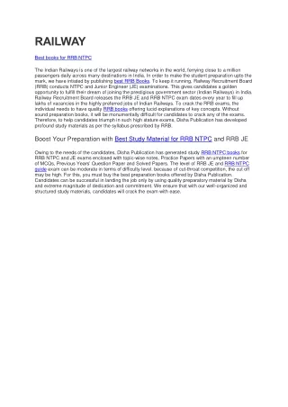
The path of steam • Superheated steam • H.P turbine • Reheater • I.P turbine • L.P turbine • Condenser • Condensate Extraction Pump • Ejector • GSC-1 • LPH- 1 • GSC-2 • LPH-2 • LPH-3 • LPH-4 • Deareator • Boiler Feed Pump • HPH-5 • HPH-6 • HPH-7 • Feed Regulating Station
Condenser: To condense the steam. • Condensate extraction pump: The condensate water is drawn from the condenser by the extraction pump. • Gland steam cooler: The seals around the rotating shaft on steam turbines are many in several ways but all leak a small amount of steam to the atmosphere. To capture this steam, many of the seals have small condensers to capture this steam. • Deareator: A deaerator is a device that is widely used for the removal of air and other dissolved gases from the feed water to steam-generating boilers.
Main Turbine The 210 MW turbine comprises of H.P, I.P and L.P cylinders. The superheated steam from the boiler passes through the emergency stop valve and control valve before entering the H.P turbine. After expanding in the 12 stages in the H.P turbine the steam returns to the boiler for reheating. The reheated steam from the boiler enters the I.P turbine via control valves and after expanding enters the I.P turbine in the l.P stage the steam expands in opposite direction to counteract the trust and then enters the condenser. The cooling water flowing through the condenser tubes condenses the steam and the condensate is collected in the hot well of the condenser.
Plant Auxiliary Maintenance Water circulation system: The water is circulated from the drum and then comes back to the drum where the water is separated from the steam and directed to the super heater. Types of water circulation system: 1. Natural circulation system 2. Forced circulation system
Ash handling Plant Hydraulic Ash Handling System: The hydraulic system carries the ash with the flow of water with high velocity through a channel and finally dumps into a sump. The hydraulic system is divided into: • Low velocity system • High velocity system In the low velocity system the ash from the boilers falls into a stream of water flowing into the sump. The ash is carried along with the water and they are separated at the sump. In the high velocity system a jet of water is sprayed to quench the hot ash. Two other jets force the ash into a trough in which they are washed away by the waterinto the sump .Hydraulic Ash handling system is used at the Badarpur Thermal Power station. Bottom Ash Collection and Disposal At the bottom of every boiler, a hopper has been provided for collection of the bottom ash from the bottom of the furnace. This hopper is always filled with water to quench the ash and clinkers falling down from the furnace. Some arrangement is included to crush the clinkers and for conveying the crushed clinkers and bottom ash to a storage site.
WATER TREATMENT PLANT Water treatment plants used in thermal power plants used in thermal power plants are designed to process the raw water to water with a very low content of dissolved solids known as ‘demineralized water’. Pretreatment Section: Pretreatment plant removes the suspended solids such as clay, silt, organic and inorganic matter, plants and other microscopic organism. The suspended solids can either be separable solids or non-separable solids(colloids). The coarse components, such as sand, silt, etc: can be removed from the water by simple sedimentation. Finer particles, however, will not settle in any reasonable time and must be flocculated to produce the large particles, which are settleable.
demineralisation This filter water is now used for demineralizing purpose and is fed to cation exchanger bed. But before that it needs to be dechorinated. This can be done in the following ways: • by passing through activated carbon filter • injecting along the flow of water an equivalent amount of sodium sulphite through some stroke pumps. The residual chlorine should be remove as it interferes with the resin. A DM plant generally consists of cation, anion and mixed bed exchangers. The final water from this process consists essentially of hydrogen ions and hydroxide ions which is the chemical composition of pure water. The DM water, being very pure, becomes highly corrosive once it absorbs oxygen from the atmosphere because of its very high affinity for oxygen absorption. Some storage is essential as the DM plant may be down for maintenance. For this purpose, a storage tank is installed from which DM water is continuously used.
Compressor house • Instrument air is required for operating various burners and other devices etc in the 210 MW units. INSTUMENT AIR SYSTEM: Control air compressors have been installed for supplying moisture free dry air required for instrument. • Air-Drying Unit • Air contains moisture which tends to condense, and causes trouble in operation of various devices by compressed air. Therefore drying of air is accepted widely in case of instrument air. The absorption towers are adequately filled with specially selected silica gel and activated alumina while one tower is drying the air.