Download

1 / 54
580 likes | 1.08k Vues
Gas Turbine Technologies for Electric Generation. by Rob Shepard, P.E. www.Neel-Schaffer.com rob.shepard@neel-schaffer.com. Gas Turbine Basics. Gas Turbines Types How They Work Applications Components of Plant Flow Paths Operation. Gas Turbine Applications. Simple Cycle

E N D
Gas Turbine Technologies for Electric Generation byRob Shepard, P.E. www.Neel-Schaffer.com rob.shepard@neel-schaffer.com
Gas Turbine Basics • Gas Turbines • Types • How They Work • Applications • Components of Plant • Flow Paths • Operation 2
Gas Turbine Applications • Simple Cycle • Combined Cycle • Cogeneration 3
Types of Gas Turbine Plants • Simple Cycle • Operate When Demand is High – Peak Demand • Operate for Short / Variable Times • Designed for Quick Start-Up • Not designed to be Efficient but Reliable • Not Cost Effective to Build for Efficiency • Combined Cycle • Operate for Peak and Economic Dispatch • Designed for Quick Start-Up • Designed to Efficient, Cost-Effective Operation • Typically Has Ability to Operate in SC Mode 4
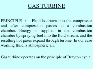
Principles ofOperation • Open Cycle Also referred to as simple cycle) • The energy contained in a flowing ideal gas is the sum of enthalpy and kinetic energy. • Pressurized gas can store or release energy. As it expands the pressure is converted to kinetic energy. Link to picture 5
Thermodynamic Fundamentals • Pressure Ratio & CT Components 7
Principles of Operation Compressor • As air flows into the compressor, energy is transferred from its rotating blades to the air. Pressure and temperature of the air increase. • Most compressors operate in the range of 75% to 85% efficiency. Combustor • The purpose of the combustor is to increase the energy stored in the compressor exhaust by raising its temperature. Turbine • The turbine acts like the compressor in reverse with respect to energy transformation. • Most turbines operate in the range of 80% to 90% efficiency. 9
Principles of OperationOverall Energy Transformations (Thermal Efficiency) • Useful Work = Energy released in turbine minus energy absorbed by compressor. The compressor requires typically approximately 50% of the energy released by the turbine. • Overall Thermal Efficiency = Useful Work/Fuel Chemical Energy *100 Typical overall thermal efficiencies of a combustion turbine are 20% - 40%. 10
Gas Turbine Applications • Simple Cycle Link to picture 11
Gas Turbine Components & Systems (cont’d) • Exhaust System • Simple Cycle Stack • Transition to HRSG • Generator • Open-Air cooled • TEWAC • Hydrogen Cooled • Starting Systems • Diesel • Motor • Static • Combustion System • Silo, Cannular, Annular • Water, Steam, DLN • Turbine • Multiple Shaft, Single Shaft • Number of Stages • Material and Manufacturing Processes Paper Towel thru compressor 16
Combustion Turbine Fuels • Conventional Fuels • Natural Gas • Liquid Fuel Oil • Nonconventional Fuels • Crude Oil • Refinery Gas • Propane • Synthetic Fuels • Chemical Process • Physical Process 17
Gas Turbine Types • Advanced Heavy-Duty Units • Advanced Aeroderivative Units 19
Gas Turbine Major Sections • Air Inlet • Compressor • Combustion System • Turbine • Exhaust • Support Systems 20
Frame 5 GT 29
GE LM2500 Aeroderivative Gas Turbine Power Turbine Section Compressor Turbine Section Compressor 30
Aeroderivative Versus Heavy Duty Combustion Turbines • Aeroderivatives • Higher Pressure Ratios and Firing Temperatures Result in Higher Power Output per Pound of Air Flow • Smaller Chilling/Cooling Systems Required • Compressor Inlet Temperature Has a Greater Impact on Output and Heat Rate • Benefits of Chilling/Cooling Systems are More Pronounced 38
Typical Simple Cycle CT Plant Components • Prime Mover (Combustion Turbine) • Fuel Supply & Preparation • Emissions Control Equipment • Generator • Electrical Switchgear • Generator Step Up Transformer • Starting System (Combustion Turbines) • Auxiliary Cooling • Fire Protection • Lubrication System 39
Typical Peaking Plant Components GSU Generator Lube Oil System Switchgear / MCC Starting Engine Fire Protection 40
Combining the Brayton and Rankine Cycles • Gas Turbine Exhaust used as the heat source for the Steam Turbine cycle • Utilizes the major efficiency loss from the Brayton cycle • Advantages: • Relatively short cycle to design, construct & commission • Higher overall efficiency • Good cycling capabilities • Fast starting and loading • Lower installed costs • No issues with ash disposal or coal storage • Disadvantages • High fuel costs • Uncertain long term fuel source • Output dependent on ambient temperature 41
How does a Combined Cycle Plant Work? Picture courtesy of Nooter/Eriksen 42
Combined Cycles Today • Plant Efficiency ~ 58-60 percent • Biggest losses are mechanical input to the compressor and heat in the exhaust • Steam Turbine output • Typically 50% of the gas turbine output • More with duct-firing • Net Plant Output (Using Frame size gas turbines) • up to 750 MW for 3 on 1 configuration • Up to 520 MW for 2 on 1 configuration • Construction time about 24 months • Engineering time 80k to 130k labor hours • Engineering duration about 12 months • Capital Cost ($900-$1100/kW) • Two (2) versus Three (3) Pressure Designs • Larger capacity units utilize the additional drums to gain efficiency at the expense of higher capital costs 44
Combined Cycle Efficiency • Simple cycle efficiency (max ~ 44%*) • Combined cycle efficiency (max ~58-60%*) • Correlating Efficiency to Heat Rate (British Units) • h= 3412/(Heat Rate) --> 3412/h = Heat Rate* • Simple cycle – 3412/.44 = 7,757 Btu/Kwh* • Combined cycle – 3412/.58 = 5,884 Btu/Kwh* • Correlating Efficiency to Heat Rate (SI Units) • h= 3600/(Heat Rate) --> 3600/h = Heat Rate* • Simple cycle – 3600/.44 = 8,182 KJ/Kwh* • Combined cycle – 3600/.58 = 6,207 KJ/Kwh* • Practical Values • HHV basis, net output basis • Simple cycle 7FA (new and clean) 10,860 Btu/Kwh (11,457 KJ/Kwh) • Combined cycle 2x1 7FA (new and clean) 6,218 Btu/Kwh (6,560 KJ/Kwh) *Gross LHV basis 45
Gas Turbine Generator Performance Factors that Influence Performance • Fuel Type, Composition, and Heating Value • Load (Base, Peak, or Part) • Compressor Inlet Temperature • Atmospheric Pressure • Inlet Pressure Drop • Varies significantly with types of air cleaning/cooling • Exhaust Pressure Drop • Affected by addition of HRSG, SCR, CO catalysts • Steam or Water Injection Rate • Used for either power augmentation or NOx control • Relative Humidity 46
Cogeneration Plant • A Cogeneration Plant • Power generation facility that also provides thermal energy (steam) to a thermal host. • Typical thermal hosts • paper mills, • chemical plants, • refineries, etc… • potentially any user that uses large quantities of steam on a continuous basis. • Good applications for combined cycle plants • Require both steam and electrical power 49
Major Combined Cycle Plant Equipment • Combustion Turbine (CT/CTG) • Steam Generator (Boiler/HRSG) • Steam Turbine (ST/STG) • Heat Rejection Equipment • Air Quality Control System (AQCS) Equipment • Electrical Equipment 50