Download
1 / 30
300 likes | 323 Vues
Learn about lightning strikes characteristics, myths on cone of protection, surge protection strategies, grounding methods, inductance equations, and conductor material considerations for radio stations.

E N D
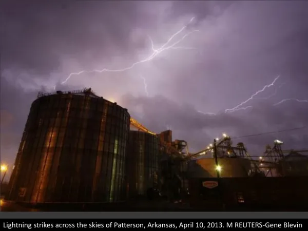
When Lightning StrikesGrounding for Amateur Radio Stations KD8DZ Mike Mickelson kd8dz@arrl.netor mickelson@denison.edu
Charged bottom of cloud ----------------------------- Electric Field ----++++++++++++++++++++++++++++++++---- Induced positive charge under cloud
Typical Characteristics of Lightning Strikes • Length of bolt: 300 meters to 1600 meters • Voltage difference: 106 to 109 volts • Average current of main strike: 40,000 amps • Return Strikes: 10,000 to 15,000 amps • Rise time: 1.8 μs • Decay time: 50 μs • Air breakdown: 3 x 10⁶ volts/meter (3000 volts/mm)
Cone of Protection Myth The following drawings depict why the so-called "cone of protection" from lightning afforded by a nearby tall object is fallacious.*
Cone of Prtection Myth The following drawings depict why the so-called "cone of protection" from lightning afforded by a nearby tall object is fallacious.*
In-House Surges due to nearby strikes Electromagnetic induction from nearby strikes can produce large voltage/current surges in residential wiring. Voltage peaks on the order of 6000 volts and currents on the order of 3000 amps with rise time of 1-2μs may occur.
Coax Line Voltage Surges Strike voltage at Top of tower 60 KV Height 60’ Coax feed at 6’ Shield voltage 10KV Coax feed below ground Shield voltage 0KV
Feed Lines and Grounding • Coax lines to be in underground conduit rather than going overhead. • In-line surge protectors on coax and shunt protectors on rotator cable preferably at the base of the tower. • Ground rods at each tower leg and additional rods spaced at twice their length and all tied together, to a perimeter ground and the AC service ground at entrance panel. • Single Point Ground at entry point to shack tied to perimeter ground. • Feed lines: Ground coax shields at base of tower.
Single point ground plane A consideration of materials for the ground plane inside the radio room leads to consideration of their respective conductivities.
Some Thoughts on Grounding Conductors • EQUATIONS FOR INDUCTANCE OF VARIOUS • COPPER CONDUCTORS • Round Copper Wire L= 2ℓ { ln(4ℓ/d) – 1} x 10-7μH • Rectangular Copper Strapping L = 2ℓ { ln[2ℓ/(b+c)] + ½}x 10-7μH • Round Copper Tubing L = 2ℓ { ln(2ℓ/r) – ¾} x 10-7μH • L (μH) • ℓ (length in meters) • d (diameter in meters) • b & c (width and thickness resp. in meters) • r (radius in meters)
Calculated Inductances L(μH) • Conductor Inductance Cross-sect. Area • # 10 copper wire: 1.27 μH/m • # 6 copper wire: 1.18 μH/m 0.021 inch2 • 1/2" copper water pipe 0.91 μH/m 0.307 inch2 • 2" x 0.011" copper strap: 0.84 μH/m 0.022 inch2 • 3/4" inch copper water pipe 0.70 μH/m 0.600 inch2 • SURFACE AREA MATTERS AT RF FREQUENCIES • Conductor Circumference /Width • # 10 copper wire: 0.32 inches 8.12 mm • # 6 copper wire: 0.51 inches 13 mm • 1/2 inch copper water pipe: 1.57 inches 39.9 mm • 2 inch x 0.011 inch copper strap: 4 inches 101.6 mm • 3/4 inch copper water pipe: 2.36 inches 59.9 mm
Effect of Surge Currents on Conductors Ohm’s Law for Inductances V = I XL = I 2π f L = I 2 π (1/T) L • Suppose you have a 10 meter (32') copper conductor: • What is the voltage difference between the ends with a surge current of 200 amps with a rise time of 2 μs. #6 Copper wire: ΔV = 754 volts 2" Copper strap: ΔV = 528 volts NOTE: However, in both cases the DC IR voltage difference is ΔV = IR = 2.6 volts, much smaller than the induced voltage...essentially negligible.
Lightning Protection • Whole house surge protectors at the entrance panel. • Surge protectors at appliance locations (Radio Room) • Single point ground connected to service ground at • entrance panel routed outside of the residence. • Surge protectors on all antenna lead-ins. • Towers grounded and connected to the single point • Ground. • Coax shields grounded to tower legs as low as • Possible.
Whole House Surge Protector Whole house surge protector
Coax Surge Protectors Ant Radio Radio Ant Radio Ant Alpha-Delta PolyphaserICE See ICE reference papers for comparison of these devices on their Web site listed below.
Ground coax shields at base of tower and connect tower leggs with ground straps to ground rods (KC9CS image)
ICE surge protector installation for three SteppIR Antennas
Coax surge protectors KD8DZ installation (in progress) Rotator surge protection SteppIR control line surge protection
The Radio Room KD8DZ Single Point Ground And feed line access
World Lightning map Data from space-based optical sensors reveal the uneven distribution of worldwide lightning strikes. Units: flashes/km2/yr. Image credit: NSSTC Lightning Team.
The Good News for most of us… Our area experiences around 45 Thunderstorm days per year.
Estimated number of lightning Strikes for a given tower height per year. A 50’ tower, indicated by the red triangle below might expect to receive one strike in a three year period.
Final Caveat! • In my opinion, no lightning protection system is full proof, especially for a direct hit although some well designed comercialites experience multiple hits without damage. • When I turn off the radio equipment, I do the following. • Unplug equipment from AC mains. • Ground all antennas. It is best to do it outside if possible to keep the effects of a lighting strike outside the station. • However, if one forgets, and if you have followed the “rules,” a near-by strike may be mitigated by your lightning protection system.
Helpful References • Scheff, W4QEJ; Lightning: Understanding it or Suffer the Consequences—Part1,QSTFeb. 2008, 92, pp 40-44 • Scheff, W4QEJ; Lightning: Understanding it or Suffer the Consequences—Part2,QST, April 2008, 92, pp 30-34 • Block, KB2UYT; Lightning Protection for the Amateur Radio Station—Part 1, QST, June 2002, 86, pp 56-59 • Block, KB2UYT; Lightning Protection for the Amateur Radio Station—Part 2, QST, July 2002, 86, pp 48-52 • Block, KB2UYT; Lightning Protection for the Amateur Radio Station—Part 3, QST, August 2002, 86, pp 53-55 • See also web sites, www.polyphaser.com, www.wrblock.com, http://www.iceradioproducts.com/, www.dxengineering.com, http://www.astrosurf.com/luxorion/qsl-lightning-protection3.htm and others. • * Additional references in each of these articles.