Circuit Elements
Circuit Elements. Prepared by:- Ronak Machhi (ID_87 )( Enrollment_042) Mehul Rami (ID_68 )( Enrollment_089) Rushabh Parmar (ID_81 )( Enrollment_063) Parth Tank (ID_88 )( Enrollment_114). Guided By: Mrs. Shital M. Pujara Asst. Professor, Electrical Department, SVIT, Vasad .

Circuit Elements
E N D
Presentation Transcript
Circuit Elements Prepared by:-RonakMachhi(ID_87)(Enrollment_042)MehulRami (ID_68)(Enrollment_089) RushabhParmar(ID_81)(Enrollment_063)Parth Tank(ID_88)(Enrollment_114) Guided By:Mrs. Shital M. PujaraAsst. Professor,Electrical Department,SVIT, Vasad.
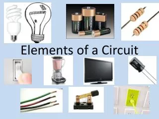
An electrical circuit is an interconnection of electrical circuit elements. • A circuit element is basically just a component that makes up a complete electrical circuit. • They are like building blocks that can be combined to create interesting circuits and model real world electronics. • Some examples include conductors, voltage sources, current sources, and resistors.
These elements can be categorized into two types: 1) Active elements and 2) Passive elements.
The most basic of the passive circuit elements are 1) Resistance, 2) Inductance and 3) Capacitance. • Passive elements do not generate (convert from non-electrical energy) any electricity. • They may either consume energy (i.e. convert from electrical form to a non-electrical form such as • heat or light), or store energy (in electrostatic and electromagnetic fields). Passive Circuit Elements
Unit: ohm, Ω Letter symbol: R , r Resistance
R i(t) v(t) (b) (a) • The common circuit symbols for the Resistor are shown in figure 1. Figure 1(a) is the common symbol used for the general resistor, especially when hand-written. • Figure 1(b) is the most general symbol for the resistor, especially when in printed form. Symbols
(c) • Figure 1(c) is the symbol used for a non-inductive resistor, when it is necessary to clearly indicate that it has been specially made to have no or negligible inductance. • A resistor made in coil form, must obviously have at least a small amount of inductance.
The basic equation governing the resistor is Ohm’s Law. v(t) = R . i(t) • This may also be written as • i(t) = G . v(t), G = 1/R • where G is the conductance. (unit: siemen, S ) • p(t) = v(t) . i(t) = R . i^2(t) • It is to be noted that p(t) is always positive indicating that power is always consumed and • energy always increases with time.
Unit: henry, H;Letter symbol: L , l Inductance
Figure 2(a) shows a coil which is the simplest symbol (and most common when hand-written) for the inductor. • A simpler representation of this is shown in figure 2(b) and is used to simplify the drawing of • circuits. Symbols i(t) v(t) (b) (a)
The symbol shown in figure 2(c) is sometimes used in printed form, especially on transformer nameplates, but is not a recommended form as it could lead to confusion with the • common resistor. (c)
The energy stored in the magnetic field of an inductor can be expressed as. • w(t) =∫ v(t) . i(t) . dt = ∫ L . i.di = ½ L. i^2 • where, W = energy stored (Joules). • L = inductance (henrys, H). • It can be seen that w(t) is dependant only on i and not on time. Thus when the current i increases, the energy consumed increases and when i decreases, the energy consumed decreases. • This actually means that there is no real consumption of energy but storage of energy.
Unit: farad, F Letter symbol: C , c Capacitance
ThecommoncircuitsymbolfortheCapacitor isshowninfigure. Symbol i(t) v(t) (a)
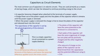
Whenavoltageisappliedacrossacapacitor,apositivechargeisdepositedononeplateanda negativechargeontheotherandthecapacitorissaidtostoreacharge. Thechargestoredisdirectlyproportionaltotheappliedvoltage. q =C.v w(t)=v(t).i(t).dt =v.CdvdtC.v.dv = ½C.v2 dt It can be seen that w(t) is dependant only on v and not on time. Thus when the voltage v increases, the energy consumed increases and when v decreases, the energy consumeddecreases. This actually means that there is no real consumption of energy but storage of energy. Thus a capacitor does not consume electrical energy, but only stores it in the electromagnetic field. Stored energy w(t) = ½C. v ^2
Summary: For a resistor, v = R i, i = G v For an inductor, v = Lpi, i=v/Lp Current through an inductor will never change suddenly. For a capacitor, v = i/Cp, i= Cpv Voltage across a capacitor will never change suddenly.
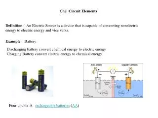
An Active Circuit Element is a component in a circuit which is capable of producing or generating energy. • Active circuit elements are thus sources of energy (or simply • sources) and can be categorized into • i) Voltage sources and ii) Current sources. • Sources can also be categorized as i) Independent sources, where the generated voltage (or current) does not depend on any other circuit voltage or current; • ii) Dependent sources, • where the generated voltage (or current) depends on another circuit voltage or current. Active Circuit Elements
For an independent voltage source (or current source), the terminal voltage (or current) would depend only on the loading and the internal source quantity, but not on any other circuit variable. • Independent Voltage Sources • Independent Current Sources Independent source
An ideal voltage source keeps the voltage across it • unchanged independent of load. • However,practicalvoltagesourceshaveadropinvoltage • acrosstheirinternal impedances. • Thevoltagedropisgenerallysmallcomparedtotheinternalemf. (Independent) Voltage Sources
An ideal current source keeps the current produced unchanged independent of load. • Practical current sources have a drop in current across their internal admittances. • The current drop is generally small compared to the internal source current (Independent)CurrentSources
A dependent voltage source (or current source) would have its terminal voltage (or current) depend on another circuit quantity such as a voltage or current. • Thus four possibilities exist. • These are • o Voltage dependent (controlled) voltage source • o Current dependent (controlled) voltage source • o Voltage dependent (controlled) current source • o Current dependent (controlled) current source Dependent Source
www.google.com • Wikipedia • Electrical technology Volume-1 by B.L.Theraja References