Ch2 Circuit Elements
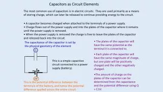
Ch2 Circuit Elements. Definition : An Electric Source is a device that is capable of converting nonelectric energy to electric energy and vice versa. Example : Battery. Discharging battery convert chemical energy to electric energy

Ch2 Circuit Elements
E N D
Presentation Transcript
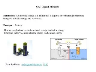
Ch2 Circuit Elements Definition : An Electric Source is a device that is capable of converting nonelectric energy to electric energy and vice versa. Example : Battery Discharging battery convert chemical energy to electric energy Charging Battery convert electric energy to chemical energy (AA) Four double-A rechargeable batteries
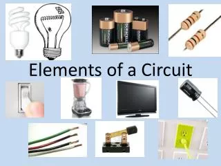
Electrical generator An electrical generator is a device that converts mechanical energy to electrical energy The source of mechanical energy may be a reciprocating or turbine steam engine, water falling through turbine or waterwheel, an internal combustion engine, a wind turbine or any other source of mechanical energy Portable Electric Generator Electric Generator
Theses souses can either deliver power like the battery when operate devices like toys, radio, mobile phone, car electric instrument,….etc. or the electric generator that deliver power to houses , cities, countries. Or absorb power like charging the battery or operating electric drill. We are going to use ideal sources to model practical sources as will be shown next. There are two type of sources that we will disuse Voltage Source Current Source We are going to use ideal sources to model practical sources as will be shown next. Those ideal sources do not exist as practical devices , they are idealized model of the actual devices
Ideal Voltage Source : is a circuit element that maintaining a prescribed voltage across its terminals regardless of the current flowing in those terminals Example : if we consider the 1.5 volt dry battery you from the market as an ideal, then you will get a 1.5 volt across the battery regards of what is connected across it or in another way the battery will supply a steady 1.2 V regardless what current flowing through it We should know that can not be possible since if the current i is large due to some load as we will see later when we discuss Ohms law, the power deliver by the small battery will be very large
We also will classified sources as Independent and Dependentsources Independent source establishes a voltage or a current in a circuit without relying on a voltage or current elsewhere in the circuit Dependent sources establishes a voltage or a current in a circuit whose value depends on the value of a voltage or a current elsewhere in the circuit We will use circle to represent Independent source and diamond shape to represent Dependent sources Dependent sources Independent source
Independent and dependent voltage and current sources can be represented as 3 A 5 V Independent voltage source Independent current source 4 ix V 4 vx A were ix is some current through an element were vx is some voltage across an element Dedependent current source Current depend on voltage Dedependent voltage source Voltage depend on current
The dependent sources can be also as 4 vx V 7 ix A were vx is some current through an element were ix is some voltage across an element Dedependent voltage source Voltage depend on voltage Dedependent current source Current depend on current
Example 2.1 for each of the following connections establish which interconnections are permissible and which violate the constrains by the ideal source Connection is valid Connection is valid Connection is not permissible Connection is valid Connection is not permissible
Example 2.2 for each of the following connections establish which interconnections are permissible and which violate the constrains by the ideal source Connection is not permissible Connection is valid Connection is not permissible Connection is valid
2.2 Electrical Resistance (Ohm’s) Georg Simon Ohm, a German physicist who is famous for defining the fundamental relationship among voltage, current, and resistance through Ohm's law
Ohm's law states that, in an electrical circuit, the current passing through a conductor, from one terminal point on the conductor to another terminal point on the conductor, is directly proportional to the potential difference (i.e. voltage drop or voltage) across the two terminal points and inversely proportional to the resistance of the conductor between the two terminal points were V = the voltage in volts (V) I = the current in amperes (A) R = the resistance in ohms (W) Most materials exhibit measurable resistance to current. The amount of resistance depend on the material. This is similar in some way when water flow in a pipe. If there is a dirt or material on the pipe it will impede ( يعيق) the flow of water.
For purpose of circuit analysis, we must reference the current in the resistor to the terminal voltage. For the passive sign convention v = Ri Otherwise we introduce a minuses sign similar to what we did when we calculated power v = - Ri
Example v = -(3)(2) = -6 V v = (3)(2) = 6 V v = -(3)(-2) = 6 V v = (3)(-2) = -6 V
The reciprocal of resistance (مقاومه) is conductance (موصل) and have the symbol G and have the unit S for (siemens) or for (mho) is spelling backward for ohm An 8 W resistor is equivalent to 1/8= 0.125 S or
We may calculate the power at the terminal of a resistor in several way First method : we use the defining equation as follows: p = vi For the passive sign convention Otherwise we introduce a minuses sign p = -vi
Second method : we express the power at the terminal of resistor in terms of the current and resistor as follows: For the non passive sign convention we have Third method : we express the power at the terminal of resistor in terms of the voltage and resistor as follows: For the non passive sign convention we have
Fourth method : we express the power at the terminal of resistor in terms of the voltage or current and conductance G as follows: For the non passive sign convention we will have identical relation as the passive sign convention
2.3 Construction of a Circuit Model This course will be focus on circuit analysis (i.e., finding voltages , currents and powers of circuit elements) However you would need to construct a model for the electric device as much as analyzing it. We are going to develop a circuit model based on the behavior of the circuit components and interconnections
2.4 Kirchhoff’s Law The objective of this course is to find (or solve) for voltages and currents in every element in the circuit Example consider the following circuit: Suppose we want to find the current i1 ? In this circuit we have 7 unknowns , namely
To solve for the 7 unknown we need 7 equations Ohms law can provide us with 4 equations, namely However Ohms equations can not be sufficient to solve for the 7 unknown, we need still 3 equations , what are these equations ?
Gustav Kirchhoff Russian scientist who first stated them in 1848 in a published paper and they are named after him as Kirchhoff Current Law (KCL) Kirchhoff Voltage Law (KVL) Kirchhoff's Current Law ( KCL): The algebraic sum of all the currents at any node in a circuit equals zero. First we have to define a node. A node is a point where two or more circuit elements meet
Kirchhoff's Current Law ( KCL): The algebraic sum of all the currents at any node in a circuit equals zero. The algebraic signify a sign on the current that is positive or negative. Since the current is a reference quantity by direction. Then we can state the following Current entering the node is positive and current leaving the node is negative OR Current entering the node is negativeand current leaving the node is positive
Example Current entering the node is positive and leaving the node is negative Current entering the node is negative and leaving the node is positive Note the algebraic sign is regardless if the sign on the value of the current
Suppose Now KCL Since electric current is a rate flow of charges then Kirchhoff's Current Law is similar to the flow of water from different direction to a water valve ( (صمام
Now we go back to our circuit Ohms law can provide us with 4 equations, namely We have 4 nodes Which can be redrawn as
Now if we apply KCL to each node we will have the followings Node 1 Node 3 Nothing new ! Node 2 Nothing new ! Node 4 Same as node 2
Now we have 5 equations, namely Ohms law can provide us with 4 equations, namely KCL provide us with 1 equations, namely We have now 5 equations , we still need two more equations Kirchhoff Voltage Law (KVL) will provide us with the other two equations as will be shown nex
Kirchhoff Voltage Law (KVL) The algebraic sum of all the voltages around any closed path in a circuit equals zero. First we have to define a closed path A closed path or a loop is defined as starting at an arbitrary node, we trace closed path in a circuit through selected basic circuit elements including open circuit and return to the original node without passing through any intermediate node more than once abea
Kirchhoff Voltage Law (KVL) The algebraic sum of all the voltages around any closed path in a circuit equals zero. First we have to define a closed path A closed path or a loop is defined as starting at an arbitrary node, we trace closed path in a circuit through selected basic circuit elements including open circuit and return to the original node without passing through any intermediate node more than once abea bceb
Kirchhoff Voltage Law (KVL) The algebraic sum of all the voltages around any closed path in a circuit equals zero. First we have to define a closed path A closed path or a loop is defined as starting at an arbitrary node, we trace closed path in a circuit through selected basic circuit elements including open circuit and return to the original node without passing through any intermediate node more than once abea bceb cdec
Kirchhoff Voltage Law (KVL) The algebraic sum of all the voltages around any closed path in a circuit equals zero. First we have to define a closed path A closed path or a loop is defined as starting at an arbitrary node, we trace closed path in a circuit through selected basic circuit elements including open circuit and return to the original node without passing through any intermediate node more than once abea bceb cdec aefa
Kirchhoff Voltage Law (KVL) The algebraic sum of all the voltages around any closed path in a circuit equals zero. First we have to define a closed path A closed path or a loop is defined as starting at an arbitrary node, we trace closed path in a circuit through selected basic circuit elements including open circuit and return to the original node without passing through any intermediate node more than once abea bceb cdec aefa abcdefa
Kirchhoff Voltage Law (KVL) The algebraic sum of all the voltages around any closed path in a circuit equals zero. The "algebraic" correspond to the reference direction to each voltage in the loop. Assigning a positive sign to a voltage rise ( - to + ) Assigning a negative sign to a voltage drop ( + to - ) OR Assigning a positive sign to a voltage drop ( + to - ) Assigning a negative sign to a voltage rise ( - to + )
Example We apply KVL as follows: Loop 1 Loop 2
Example We apply KVL as follows: Loop 1 Loop 2 Loop 3 However we notice that KVL on Loop 3 is only the summation of Loop 1 and Loop 2 Therefore only two KVL equations are valid Loop 1 Loop 2
Now we go back to our circuit Now we have 7 equations, namely Ohms law provide us with 4 equations, namely KCL provide us with 1 equations, namely KVL provide us with 2 equations, namely Now we can solve the 7 equations to obtain the 7 variables
We can think of KVL as a gas that distribute pressure gas to different houses. When it leaves the station it is full of gas. Then it start delivering the gas to each house depend on the size of the house
Example 2.6 for the circuit shown apply KCL to each node a, b, c, and d. Note there is no connection dot at the center of the diagram (i.e, no node). The 4 W branch crosses the branch containing the ideal current ia Applying KCL to nodes a, b, c, and d , we have
Example 2.7 for the circuit shown apply KVL to each designated path in the circuit
Example 2.7 for the circuit shown apply KVL to each designated path in the circuit
Example 2.7 for the circuit shown apply KVL to each designated path in the circuit
Example 2.7 for the circuit shown apply KVL to each designated path in the circuit
Example 2.7 for the circuit shown apply KVL to each designated path in the circuit
Example 2.7 for the circuit shown apply KVL to each designated path in the circuit
Example 2.7 for the circuit shown apply KVL to each designated path in the circuit
Example 2.8 for the circuit shown use Kirchcoff’s laws and Ohm’s law to find io? Solution We will redraw the circuit and assign currents and voltages as follows Since io is the current in the 120 V source , therefore there is only two unknown currents in the circuit namely: io and i1
Therefore we need two equations relating io and i1 Applying KCL to the circuit nodes namely a,b and c will give us the following Node a Nothing new ! Node b Node c The same as node b Therefore KCL provide us with only one equation relating io and i1 namely We need another equation to be able to solve for io That equation will be provided by KVL as shown next
We have three closed loops However only one loop that you can apply KVL to it namely abca Since the other two loops contain a current source namely 6 A and since we can not relate the voltage across it to the current through it , therefore we can not apply KVL to that loop Applying KVL around loop abca clockwise direction assigning a positive sign to voltage drops ( + to - ) and negative sign to voltage rise , we have Combinning this with the KCL equation we have two equations and unknowns which can be solved simultaneously to get io=-3 A i1=3 A