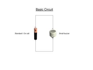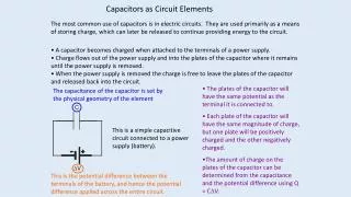
Basic Circuit Elements
Basic Circuit Elements. Standard TTL Small-Scale Integration: 1 chip = 2-8 gates Requires numerous chips to build interesting circuits Alternative: Complex chips for standard functions Single chip that performs very complex computations PALs/PLAs: Programmable for arbitrary functions

Basic Circuit Elements
E N D
Presentation Transcript
Basic Circuit Elements • Standard TTL Small-Scale Integration: 1 chip = 2-8 gates • Requires numerous chips to build interesting circuits • Alternative: Complex chips for standard functions • Single chip that performs very complex computations • PALs/PLAs: Programmable for arbitrary functions • Multiplexer/Decoder/Encoder: Standard routing elements for interconnections
Programmable Logic Arrays (PLAs/PALs) Pre-fabricated building block of many AND/OR gates (or NOR, NAND) "Personalized" by making or breaking connections among the gates Programmable Array Block Diagram for Sum of Products Form
Benefits of PLAs Key to Success: Shared Product Terms Equations F0 = A + B C F1 = A C + A B F2 = B C + A B F3 = B C + A Example: Input Side: 1 = asserted in term 0 = negated in term - = does not participate Personality Matrix Output Side: 1 = term connected to output 0 = no connection to output
Unprogrammed PLA All possible connections are available before programming
Programmed PLA Unwanted connections are "blown"
Simplified PLA Diagrams Short-hand notation so we don't have to draw all the wires! Notation for implementing F0 = A B + A' B' F1 = C D' + C' D
PLA Example Multiple functions of A, B, C F1 = A B C F2 = A + B + C F3 = A B C F4 = A + B + C F5 = A xor B xor C F6 = A xor B xor C F1 F2 F3 F4 F5 F6
PALs vs. PLAs What is difference between Programmable Array Logic (PAL) and Programmable Logic Array (PLA)? PAL concept: constrained topology of the OR Array A given column of the OR array has access to only a subset of the possible product terms PLA concept — generalized topologies in AND and OR planes
PAL Example X = BCD + ABCD + AD Y = CD + AB + ACD + BCD
A A AB AB 00 01 11 10 00 01 11 10 CD CD 00 00 01 01 D D 11 11 C C 10 10 B B K-map for EQ K-map for NE A A AB AB 00 01 11 10 00 01 11 10 CD CD 00 00 01 01 D D 11 11 C C 10 10 B B K-map for LT K-map for GT PLA Design Example: 2’s Comp. Compare EQ NE LT GT
D/A Ear A/D E M B S Mouth Bell Start Design Example: Basic Telephone System • Put together a simple telephone system
E M B S E M B S E M B S E M B S E M B S Basic Telephone System (cont.) • Multiple subscribers, one operator. • Operator controls all connections Operator
Standard Circuit Elements • Develop implementations of important “Building Blocks” • Used in Networks, Computers, Stereos, etc. • Multiplexer: Combine N sources onto 1 wire • Decoder: Determine which input is active • Encoder: Convert binary to one-of-N wires
0 D0 D1 D2 D3 D4 D5 D6 D7 1 2 3 3:8 dec 4 5 6 7 S S S 2 1 0 A B C Decoders • Used to select one of 2N outputs based on N input bits • Input: N bits; output: 2N outputs -- only one is active • A decoder that has n inputs and m outputs is referred to as an n x m, N:M, or n-to-m decoder • Example: 3-to-8 decoder
Enabled Decoder Implementation • Active High enable
Decoder Expansion • Construct a 4:16 decoder using 2:4 decoders
0 1 2 3 4 5 6 4:16 7 En dec 8 9 10 1 1 12 13 14 15 S S S S 3 2 1 0 Decoders in General Logic Implementation • Implement F = WXZ + XZ w/4x16 Decoder
Encoders • Performs the inverse operation of decoders • Input: 2N or less lines -- only 1 is asserted at any given time • Output: N output lines • Function: the output is the binary representation of the ID of the input line that is asserted
Encoder Implementation • 4:2 Encoder
Priority Encoder • Use priorities to resolve the problem of 2 or more input lines active at a time. • One scheme: Highest ID active wins • Also add an output to identify when at least 1 input active
Multiplexer • An element that selects data from one of many input lines and directs it to a single output line • Input: 2N input lines and N selection lines • Output: the data from one selected input line • Multiplexer often abbreviated as MUX
Multiplexer Implementation • 4:1 MUX
Multiplexer Expansion • Construct a 16:1 MUX using 4:1 MUX’s
0 1 2 F 8:1 3 MUX 4 5 6 7 S2 S1 S0 Multiplexers in General Logic • Implement F = XYZ + YZ with a 8:1 MUX
0 F 1 4:1 2 MUX 3 S1 S0 Multiplexers in General Logic (cont.) • Implement F = XYZ + YZ with a 4:1 MUX