Basic circuit theory
Understand the fundamentals of electric circuits, including resistors, Ohm's law, circuit analysis methods, and Kirchhoff's laws. Learn about circuit models, mathematical techniques, and circuit element construction.


Basic circuit theory
E N D
Presentation Transcript
Sensors Technology – MED4 Basic circuit theory Lecturer: Smilen Dimitrov
Introduction • The model that we introduced for ST
Introduction • We have discussed • The units of voltage, current and resistance, in terms of electric circuits • The definition of an elementary electric circuit • Ohm’s law
Resistors • Construction of resistors • Different sizes for different power ratings • As far as construction of resistors goes, generally we can discern • Carbon Composition Resistors • Film Resistors • Carbon Film Resistors • Metal Film Resistors • Metal Oxide Resistors • Wire Wound Resistors
Resistors – color code • Ratings of resistors – written as color code
Basic circuit theory • Electrical circuit is a mathematical model that approximates the behavior of an actual electrical system. Circuit theory [consists of] models and mathematical techniques • Circuits (also known as 'networks') are collections of circuit elements and wires. • Electric circuits will be considered as graphs of two types of elements: nodes and branches. The branches, which are electric components like resistors and voltage sources, connect the nodes, which can be viewed as representatives of voltage potentials. • Circuit analysis is concerned with the computation of voltages and currents in a circuit for a certain excitation. There are various methods for equation formulation for a circuit. These are based on three types of equations found in circuit theory: • equations based on Kirchhoff's voltage law (KVL), • equations based on Kirchhoff's current law (KCL), and • branch constitutive equations.
Basic circuit theory • Solving a set of equations that represents a circuit is straightforward, if not always easy. However, developing that set of equations is not so easy. • The two commonly taught methods for forming a set of equations are the node voltage (or nodal) method and the loop-current (or mesh) method.
Basic circuit theory • Conventions – schematics • While analysing a state of a circuit, one also writes the direction of current and the polarity of voltage in a schematic
Basic circuit theory • Marking voltage • Technical and real direction of current
Basic circuit theory • Active and passive convention: the elements within a circuit will either: control the flow of electric energy or respond to it. • Open and Closed Circuits • 'Shorting' an element • Kirchhoff's laws are expressions of conservation laws: in physics, a conservation law states that a particular measurable property of an isolated physical system does not change as the system evolves. A partial listing of conservation laws that are said to be exact laws, or more precisely have never been shown to be violated.
1st Kirchhoff (current) law - KCL • Statement of the law of conservation of charge – “what goes in, must go out” • Or in particular – the sum of currents going in and out of a given node, is always equal to zero.
2nd Kirchhoff (current) law - KVL • Statement of the law of conservation of energy • The directed sum of the voltages (electrical potential differences)around a circuit (loop)must be zero. • Sum of voltages around every closed loop in the circuit must equal zero. A closed loop has the obvious definition: Starting at a node, trace a path through the circuit that returns you to the origin node. • An element's voltage enters with a plus sign if traversing the closed path, we go from the positive to the negative of the voltage's definition.
Ohms law and equivalence principle (Thevenin) • Ohms law here is the branch equation for a resistor: • Equvalence principle - Thevenin theorem – for resistive circuits, it is possible that circuits are represented through an equivalent circuit – a ”black box”
Measurement • Voltmeter is connected ”across” two points, ampermeter is connected ”through” a point
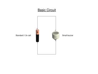
Elementary electric circuit • Simplest to solve using circuit theory: • Output voltage is simply equal to input voltage !
Series connection – the voltage divider • Our basic circuit in this course.
Series connection – the voltage divider • Our basic circuit in this course. The input voltage E is divided in two output voltages U1 and U2 The output voltage U2 is the input voltage E, divided by
Equivalent resistance of series connection • What does the power supply E ”see”? • The equivalent resistance for resistors in series is, as a value, always dominated by the biggest resistor in the sum
Parallel connection – current divider The input current I is divided in two output currents I1 and I2 -> The output voltage is the same as the input voltage !
Equivalent resistance of parallel connection • What does the power supply E ”see”? • The equivalent resistance for resistors in parallel is, as a value, always dominated by the smallest resistor in the parallel combination.
Combined connection To solve the circuit (find all the currents and voltages, we must set a system of 6 equations, using Kirchoff Laws and brach equations (Ohms law). The output voltage will be:
Combined connection Easier way to solve the circuit: Find equivalent parallel resistance And solve a voltage divider.... The output voltage will be:
Combined connection • Important – when Rih is almost infinite; simulates a connection of a voltage divider to the data acquisition (Arduino)!
Analysis methods • Just a mention of two analysis methods for solving complicated circuits: • Node Voltage Method (Nodal analysis) • Loop Current Method (Mesh current analysis)