Electric Circuit Theory
Electric Circuit Theory. The Atom & Ohm’s Law. First, lets look at the Atom. Orbit. Electron. Neutron. Proton. Nucleus. Valence Electrons. Electronics focuses on the electrons in the Valence Shell. Valence electrons are more loosely bound to the atom and easier to move.


Electric Circuit Theory
E N D
Presentation Transcript
Electric Circuit Theory The Atom & Ohm’s Law
First, lets look at the Atom Orbit Electron Neutron Proton Nucleus
Valence Electrons Electronics focuses on the electrons in the Valence Shell Valence electrons are more loosely bound to the atom and easier to move Too tightly bound to easily move
Silver Gold Copper Conductors 3 or Less Electrons in the Valence Shell What makes a good wire?? 2nd 1st 3rd
1. Superconductors 2. Gold 3. Silver 4. Copper Top 4 conductors
HTS – High Temperature Superconductors 2001 Japan – magnesium diboride – 39 degrees Kelvin "Second generation" HTS wire can carry the same amount of current as copper wire hundreds of times as thick.
Oxygen Neon Insulators 5 or More Electrons in the Valence Shell Wood, Rubber and even PURE H20 all have an atomic structure where there are more than five electrons “free” to move Yes..There are Neon signs but…they only work at VERY high VOLTAGES
Digital Electronics, Silicon Valley, “The Chip”, Computers, Cell Phones, and…virtually all modern electronics… Germanium Silicon Semi-Conductors 4 Electrons in the Valence Shell Their chemistry can be “played with” to make them a conductor one instant and an insulator the next…On..Off….0…1 etc.
Insulator Semiconductor Conductors
New words.. • Load : Any Device that uses the electrical energy to perform a task or do work. Light Bulb, Fan, Computer, New York City, etc. • NOTE: All Loads have a value of Resistance they need to have the electricity pushed through them the higher the load, the higher the value of resistance assigned to them.
New words… • Transducer: any device that turns one form of energy into another. • Most loads are transducers as they generally turn the electrical energy into one more useable by humans. i.e. fans, heaters, lights, etc.
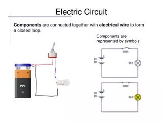
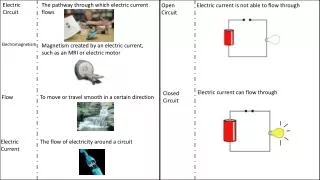
A basic circuit… + 2. Load _ 1. Power Source 3. Pathway In this Closed Loop circuit electrons flow from negative to positive THROUGH the load and work gets done
The four parts of a basic circuit… + 2. Load _ 4. Control 1. Power Source 3. Pathway If the pathway from negative to positive is broken no electrons will flow and no work gets done. This is the function of every switch; to control the flow of electrons by “opening” and “closing” the circuit i.e. “OFF and ON”
What is Voltage? Named after Alessandro Volta who invented the first practical battery in 1799 "Reason to Move" or "Push" Potential - Electrons don’t “want” to move from one atom to another. Any force chemical, magnetic, mechanical or whatever that gives them a “Push” or “Reason to move” from one atom onto another is called a voltage… But REMEMBER… just because you are pushing on something does not mean that it will move… there may be too much resistance to movement present even if you are pushing really hard..
What is Resistance? No this is not named after anyone named “Resist” It is as the name implies… ”Opposition to Movement” All loads and all wires except superconductors have some amount of resistance "Opposition to Movement" Resistance is Measured in OHMS and this unit of measurement IS named after the mathematician who discovered the most fundamental law governing the study of electricity… OHM’s LAW. His name was Georg Simon OHM
What is Amperage? Named after Andre Marie Ampere a mathematician who formulated theories that greatly helped solidify the link between electricity and magnetism "Amount Per Time" This is the Dangerous part of electricity. Roughly 0.5 Amps of electricity is enough to kill a person. Yes…this IS an Amp but not the kind intended in this lesson… However, the more “Amps” that run through it, the louder it gets…
Mind Teaser… Coalson and Houston’s Discipline Plan…If you mess up in class..we take you to the beach tie you to a post, then call the weather bureau and order a tsunami to head straight toward where your are standing…Our Rule… In order to be let back into class you MUST withstand being hit with 10,000,000,000 gallons of water!!! Question... How can you follow the rules an still be sure that you will survive??
Answer.. • Yes!! Request that you get hit ONE GLASS at a TIME!! You’ll be a bit wrinkled but you will survive • This is an example of the difference between Voltage and Amperage. 10,000 Volts is only “Dangerous” because like all that water, it has the “potential” to do some serious damage… But that is ONLY if it is ALL unleashed at once! • Soooo… High Voltage with LOW Amperage can be safe but HIGH Amperage is ALWAYS dangerous • Soooo… Amount Per Time is what is dangerous
Current flow • Electrons flow from the negative terminal to the positive terminal through a circuit. • Because, by convention electrons are negatively charged, this is a negative current flow. • Thus conventionally, engineers talk of a positive current flow from the positive terminal to the negative one, even though in practice this is due to negatively charged electrons flowing the other way.
Ohm’s Law: The relationship between Voltage, Resistance, and Amperage Lets Use an Analogy! A power source initiates electric flow by creating a Voltage, or a difference in potential between two points of a closed circuit. Voltage of course, is a dependent variable…. The circuit load, the other dependent variable, measured in units of resistance, is what opposes this push of electrons through the circuit… Blah blahblahblah
Ohm’s Law Analogies Voltage or “Reason for electrons to Move” Resistance to Movement Amperage; The number of Mice per Unit of time that make it to the cheese Electrons
Ohm’s Law Analogies Voltage Resistance Amperage = 5 mice /Second Electrons Use ye' smarts... What are TWO things that can be done to INCREASE the Amperage?
Ohm’s Law Analogies Voltage Resistance Amperage = 50 mice /Second Electrons DECREASING resistance in a circuit will raise the amperage in the same circuit proportionally OR…
Ohm’s Law Analogies Resistance Amperage = 50 mice / Second Voltage Electrons Leaving the resistance alone but INCREASING the voltage will also raise the amperage proportionally
Ohm’s Law Analogies Voltage Resistance Amperage = 5 mice /Second Electrons Use ye' smarts... What are TWO things that can be done to DECREASE the Amperage?
Ohm’s Law Analogies Voltage Amperage = 1 mice /Second Electrons Resistance INCREASING resistance in a circuit will decrease the amperage in the same circuit proportionally OR…
Ohm’s Law Analogies Voltage Amperage = 1 mice /Second Electrons Resistance DECREASING voltage in a circuit will decrease the amperage in the same circuit proportionally
What Happens when… Resistance Amperage ?? Voltage Amperage ??
What Ohm Proved Resistance Amperage ?? Voltage Amperage ?? Inversely Proportional Directly Proportional
Ohm’s Law Analogy dsgdsafg dsgdsafg dsgdsafg Two Ways to INCREASE Amperage: Jdsfkljsadfkljsafjdkljsadfkljsadfjfjdskldsajsdafd Fadfadfadfadsssdkjsf;flkjdf;lkjadf;lkajdf;laskdjf Two Ways to DECREASE Amperage: Dnfkljasdihjiafheansfnfeklanwfiejenfansdfnasfd Fakjdf;lakjdfl;akdjfl;akdjflkkjfkdkjfliheirouaepoo Your Turn… • Assignment Title, • Your Name, • Date, • Class Period, • Teacher’s Name HOMEWORK ASSIGNMENT #1 Create your Own Ohm’s Law analogy on a single sheet of paper. It must contain: • A drawing with labels of each part of the analogy • electrons • resistance • amperage • voltage • And a written description of the TWO ways in which the amperage can be raised and the TWO ways amperage can be lowered. Name Date Period Teacher’s Name dsgdsafg
E Use this simple memory device I R Ohm’s Law (The Math) E = Voltage I = Amperage R = Resistance E = I*R R = E/I I =E/R You could remember all three of these…..or…
Ohm’s Law Cover up what you want to find and the formula is presented to you. E Divide Line I R Multiply Line How do you remember the chart? “Every Idiot Remembers” This of course means that if you forget it you are a genius!
Ohm’s Law • “OK” …you say….I get that “R” is for Resistance but WHY the E and I?? • Before Volts were named after Volta, it was simply called “Electro-motive Force” or backwards, “the force that moves electricity”… SOO…. “E” just stuck to represent voltage when doing calculations
Ohm’s Law • Alright but what about “I”?? • Before Amperage was named after Ampere it was called “Intensity”
Let’s do math! Pretend one of your classmates, ( go ahead pick one), placed their head where normally a light bulb would go in a circuit. Their head is now the “load”. Every load has an amount or value of resistance to electron movement.
Let’s do math! In the language of Baseball……He is outta’ there! In the language of Food……He is Toast! Ya’ get the picture… 10 Ohms 100 V What two things can you do to save this person?
Only Three Circuits to Learn… There are only three ways to hook up an electric circuit. If you learn all three and how electricity moves through them, then you understand the fundamental principals of how ALL of electronics works. Other stuff you will learn along the way... Will lead to YOU proving WHY dozens of things should not be plugged into the same outlet.
Series Circuit • Only ONE pathway from negative to positive • If one light bulb burns out the rest will not work and you are in serius trouble The “Extra Bulb”
Parallel Circuit • More than ONE pathway from negative to positive • If one light bulb burns out it will not affect the rest
Series-Parallel Circuit • Both Series and Parallel sections within the circuit. • If one light bulb burns out it may affect other parts of the circuit
Analog vs. Digital • Analog • a variable signal continuous in both time and amplitude • Digital • one that uses discrete values representing numbers or non-numeric symbols such as letters or icons, for input, processing, transmission, storage, or display, rather than a continuous spectrum of values