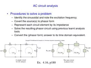
AC Circuit Theory
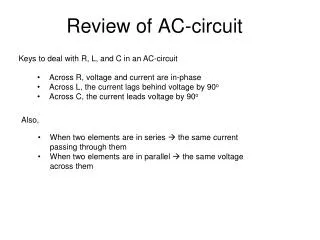
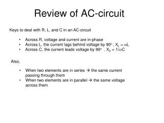
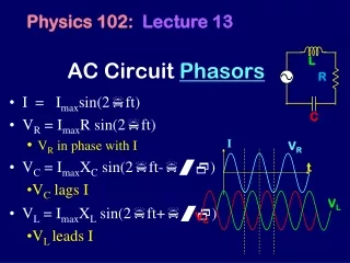
AC Circuit Theory. Amplitude Phase. V=V 0 sin( ω t) V=V 0 cos( ω t) V=V 0 sin( ω t+ φ ). I. …capacitor…. C. I. Voltage lags current by /2. L. Apply AC current to a resistor…. I=I 0 sin( ω t) V R =IR=I 0 Rsin( ω t). I. R. …and inductor. Voltage leads current by /2.


AC Circuit Theory
E N D
Presentation Transcript
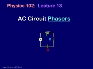
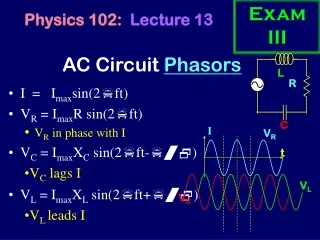
AC Circuit Theory Amplitude Phase V=V0sin(ωt) V=V0cos(ωt) V=V0sin(ωt+φ)
I …capacitor… C I Voltage lags current by /2 L Apply AC current to a resistor… I=I0sin(ωt) VR=IR=I0Rsin(ωt) I R …and inductor Voltage leads current by /2
Adding voltages + R1 I0sin(ωt) V(t)? R2 Kirchoff’s Voltage LawandOhm’s law R3 - V=I0R1sin(ωt)+I0R2sin(ωt)+I0R3sin(ωt) =I0(R1+R2+R3)sin(ωt)
Adding voltages + R1 I0sin(ωt) V(t) =VR+VC + C1 voltages out of phase…
Complex numbers in AC circuit theory Im(z) |z|sin(θ) θ j2=–1 Reason: ‘i’ is already taken |z|cos(θ) Re(z)
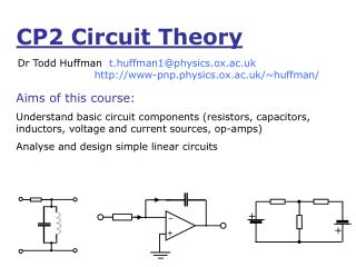
Complex Impedance The ratio of the voltage across a component to the current through it when both are expressed in complex notation I=I0sin(ωt) I=I0ejωt
Complex Impedance Real part: resistance (R) Imaginary part: reactance Ohm’s law jωL R
Series / parallel impedances L C R Z1=R Z2=jωL Impedances in series: ZTotal=Z1+Z2+Z3… Impedances in parallel Z1 Z2 Z3
RC low pass filter R + + VOUT VIN 1/(jwC) - - ZR ZC
RL high pass filter R + + VOUT VIN jwL - - Here is a slight trick: Get comfortable withthe complex result.
Bode plot (-3dB)
Decibels Logarithm of power ratio VOUT/VIN dB 10 20 1 0 0.1 –20 0.01 –40 0.001 –60
Something Interesting • Capacitor • At low frequencies (like DC) Open circuit • Not a surprise, it’s got a gap! • At high frequencies (“fast”) Short circuit! • Inductor • At low frequencies Short circuit • Not a surprise, it’s just a wire really • At high frequencies Open circuit! • Sometimes this can help you with your intuition on the circuit’s behaviour.
Go to black Board and Explain Phasors
LRC series circuit L C R I0ejωt Purely resistive at φ=0 Z=R
LRC parallel circuit I0ejωt R C L
Bandpass filter R + + VIN VOUT C L
Bandpass filter build a radio filter C=10nF L=12.2μH f0=455kHz Δf=20kHz R=389Ω
R L I(t) C LCR series circuit – current driven I(t)=I0ejωt Freq.Wild Stuff going on! NOT a Very Good Idea
LCR series circuit – voltage driven V(t)=V0ejωt R L V(t) C
R/L=106 R/L=105
Q value No longer on CP2 syllabus (moved to CP3) Not always helpful Frequency at resonance Diff. in Freq. to FWHM High Q value – narrow resonance
Q value For what we did last time. Dw High Q value – narrow resonance
R L I(t) C LC circuit – power dissipation Power is only dissipated in the resistor proof – power dissipated inductor and capacitor – none reactance
LRC Power dissipation R I = V(t) V(t) L Z=Z0ejφ C Instantaneous power
Power dissipation cosφ = power factor
On black board But then go ahead and flip to next slide now anyway. Power in complex circuit analysis
Power factor Resistive load Z=R cosφ=1 Reactive load Z=X cosφ=0
Bridge circuits To determine an unknown impedance Z1 Z3 VA VB V(t) V Z4 Z2 Bridge balanced when VAVB=0
Phasors and stuff Backup Slides
I C Phasors I=I0sin(ωt) VR=IR=I0Rsin(ωt) I R I L
VT Phasors V0cos(ωt) V0sin(ωt) ωt C R I0sin(ωt)
RC phasors C R I0sin(ωt) VT=V0sin(ωt+φ) I0sin(ωt) V0sin(ωt+φ)
Phasors – mathematics VT=V0sin(ωt+φ) Asin(ωt) + Bcos(ωt) = Rsin(ωt + φ) Rsin(ωt + φ) = Rsin(ωt)cos(φ) + Rcos(ωt)sin(φ) A=Rcos(φ) B=Rsin(φ) A2 + B2 = R2 B/A = tan(φ)
RL phasors L R I0sin(ωt) VT=V0sin(ωt+φ) V0sin(ωt+φ) I0sin(ωt)
RL filter R VOUT VIN L high pass filter
Phasors: RC filter R VOUT VIN C low pass filter