Download

1 / 27
380 likes | 742 Vues
Circuit Theory Laws. Circuit Theory Laws. This presentation will Define voltage, current, and resistance. Define and apply Ohm’s Law. Introduce series circuits. Current in a series circuit Resistance in a series circuit Voltage in a series circuit Define and apply Kirchhoff’s Voltage Law.

E N D
Circuit Theory Laws • This presentation will • Define voltage, current, and resistance. • Define and apply Ohm’s Law. • Introduce series circuits. • Current in a series circuit • Resistance in a series circuit • Voltage in a series circuit • Define and apply Kirchhoff’s Voltage Law. • Introduce parallel circuits. • Current in a parallel circuit • Resistance in a parallel circuit • Voltage in a parallel circuit • Define and apply Kirchhoff’s Current Law.
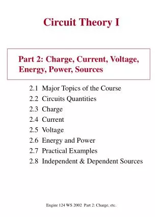
Electricity – The Basics An understanding of the basics of electricity requires the understanding of three fundamental concepts. • Voltage • Current • Resistance A direct mathematical relationship exists between voltage, resistance, and current in all electronic circuits.
Voltage, Current, & Resistance Current – Current is the flow of electrical charge through an electronic circuit. The direction of a current is opposite to the direction of electron flow. Current is measured in AMPERES (AMPS). Andre Ampere 1775-1836 French Physicist
Voltage Voltage – Voltage is the electrical force that causes current to flow in a circuit. It is measured in VOLTS. Alessandro Volta 1745-1827 Italian Physicist
Current Current – Current is the flow of electrical charge through an electronic circuit. The direction of a current is opposite to the direction of electron flow. Current is measured in AMPERES (AMPS). Andre Ampere 1775-1836 French Physicist
First, An Analogy The flow of water from one tank to another is a good analogy for an electrical circuit and the mathematical relationship between voltage, resistance, and current. Force: The difference in the water levels ≡ Voltage Flow: The flow of the water between the tanks ≡ Current Opposition: The valve that limits the amount of water ≡ Resistance Force Flow Opposition
Anatomy of a Flashlight - + Switch Switch Light Bulb Light Bulb D - Cell Battery Battery Block Diagram Schematic Diagram
Flashlight Schematic Open circuit (switch open) No current flow Lamp is off Lamp is resistance, but is not using any energy • Closed circuit (switch closed) • Current flow • Lamp is on • Lamp is resistance, uses energy to produce light (and heat) Current Resistance Voltage - + - +
Current Flow • Conventional Current assumes that current flows out of the positive side of the battery, through the circuit, and back to the negative side of the battery. This was the convention established when electricity was first discovered, but it is incorrect! • Electron Flow is what actually happens. The electrons flow out of the negative side of the battery, through the circuit, and back to the positive side of the battery. Conventional Current Electron Flow
Engineering vs. Science • The direction that the current flows does not affect what the current is doing; thus, it doesn’t make any difference which convention is used as long as you are consistent. • Both Conventional Current and Electron Flow are used. In general, the science disciplines use Electron Flow, whereas the engineering disciplines use Conventional Current. • Since this is an engineering course, we will use Conventional Current . Conventional Current Electron Flow
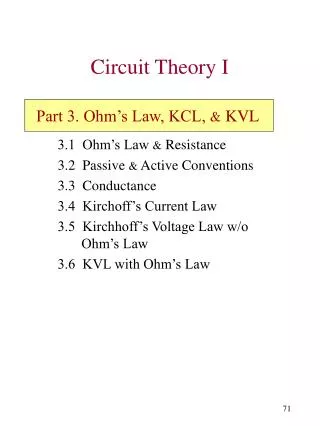
Ohm’s Law • Defines the relationship between voltage, current, and resistance in an electric circuit • Ohm’s Law: Current in a resistor varies in direct proportion to the voltage applied to it and is inversely proportional to the resistor’s value. • Stated mathematically: V + - I R Where: I is the current (amperes) V is the potential difference (volts) R is the resistance (ohms)
Ohm’s Law Triangle V V V I I I R R R
Example: Ohm’s Law • Example: • The flashlight shown uses a 6 volt battery and has a bulb with a resistance of 150 . When the flashlight is on, how much current will be drawn from the battery?
Example: Ohm’s Law • Example: • The flashlight shown uses a 6 volt battery and has a bulb with a resistance of 150 . When the flashlight is on, how much current will be drawn from the battery? V I R Solution: Schematic Diagram IR + - VT = VR
Circuit Configuration Components in a circuit can be connected in one of two ways. Parallel Circuits Both ends of the components are connected together. There are multiple paths for current to flow. Series Circuits • Components are connected end-to-end. • There is only a single path for current to flow. Components (i.e., resistors, batteries, capacitors, etc.)
Series Circuits Characteristics of a series circuit • The current flowing through every series component is equal. • The total resistance (RT) is equal to the sum of all of the resistances (i.e., R1 + R2 + R3). • The sum of all of the voltage drops (VR1 + VR2 + VR2) is equal to the total applied voltage (VT). This is called Kirchhoff’s Voltage Law. VR1 IT + - + + VR2 VT - - - + RT VR3
Example: Series Circuit • Example: • For the series circuit shown, use the laws of circuit theory to calculate the following: • The total resistance (RT) • The current flowing through each component (IT, IR1, IR2, & IR3) • The voltageacross each component (VT, VR1, VR2, & VR3) • Use the results to verify Kirchhoff’s Voltage Law. VR1 IT + - IR1 + + VR2 VT IR2 - - IR3 - + RT VR3
Example: Series Circuit Solution: Total Resistance: V I R Current Through Each Component:
Example: Series Circuit Solution: Voltage Across Each Component: V I R
Example: Series Circuit Solution: Verify Kirchhoff’s Voltage Law:
Parallel Circuits Characteristics of a Parallel Circuit • The voltage across every parallel component is equal. • The total resistance (RT) is equal to the reciprocal of the sum of the reciprocal: • The sum of all of the currents in each branch (IR1 + IR2 + IR3) is equal to the total current (IT). This is called Kirchhoff’s Current Law. IT + + + + VR1 VR2 VR3 VT - - - - RT
Example: Parallel Circuit • Example: • For the parallel circuit shown, use the laws of circuit theory to calculate the following: • The total resistance (RT) • The voltageacross each component (VT, VR1, VR2, & VR3) • The current flowing through each component (IT, IR1, IR2, & IR3) • Use the results to verify Kirchhoff’s Current Law. IT IR1 IR2 IR3 + + + + VR1 VR2 VR3 VT - - - - 23 RT
Example: Parallel Circuit Solution: Total Resistance: Voltage Across Each Component:
Example: Parallel Circuit Solution: Current Through Each Component: V I R
Example: Parallel Circuit Solution: Verify Kirchhoff’s Current Law:
Summary of Kirchhoff’s Laws • Kirchhoff’s Voltage Law (KVL): • The sum of all of the voltage drops in a series circuit equals the total applied voltage. • Kirchhoff’s Current Law (KCL): • The total current in a parallel circuit equals the sum of the individual branch currents. Gustav Kirchhoff 1824-1887 German Physicist