PIC MicroController
PIC MicroController. Processor Architectures. Von Neumann. CPU. 8-Bits. Program and Data Memory. Harvard. CPU. 8-Bits. Data Memory. 12/14/16-Bits. Program Memory. Fetches instructions and data from one memory. Limits Operating Bandwidth.

PIC MicroController
E N D
Presentation Transcript
Processor Architectures Von Neumann CPU 8-Bits Program and Data Memory Harvard CPU 8-Bits Data Memory 12/14/16-Bits Program Memory • Fetches instructions and data from one memory. • Limits Operating Bandwidth Two separate memory spaces and addresses for instructions and data. • Increases throughput • Different program and data bus widths are possible • Instruction Pipelining easy
Memory - General Concepts and Use • ROM stores the fixed program within a microcontroller and also any fixed data • PROM/MASK ROM • High volume, fixed design, custom masks • EPROM • Erasable using ultraviolet. Long, but limited, lifetime. Limited number of erase/program cycles (100). Programmed using custom programmer. • EEPROM • In circuit programming possible. Individual bytes can be erased and rewritten. Up to 100,000 cycles. • FLASH • In circuit reprogramming, based upon erasing and re-writing fixed size sectors (64/512 bytes etc). Only withstand 100 to 10,000 cycles.
Alpha 21264 588 pins 64-bit Data Path 7-stage pipeline >15M Transistors Needs 60W of Power 4 Instructions/Cycle Up to 1Ghz Down to .18 micron PIC 12C804 8 pins 8-bit Data Path 2-stage pipeline ~5,000 Transistors Needs 80uW – 13mW 1 Inst – 1 or 2 Cycles Up to 4Mhz Down to .7 micron Architectural features
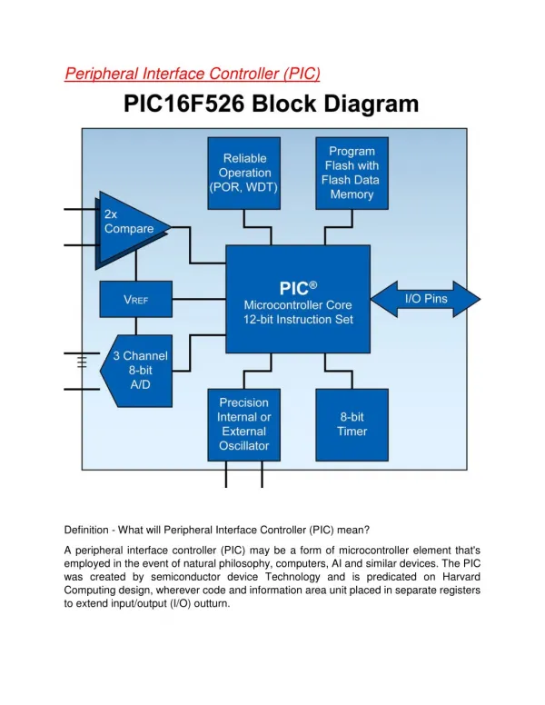
PIC • Developed by Arizona Microchip • Different types available ranging from 18PIN DIP devices with 12 I/O lines, 1 timer and limited facilities • Up to 68 pin devices with 3 timers, built in 6 channel ADC, PWM and serial modules. • We will focus on the 16F84 and the 16F877 • Development Tools • MPLab development IDE • PICStart Plus programmer • PICDEM-2 demo board • PIC ICD in circuit debugger • PIC-ICE In circuit emulator
PIC Architecture - Overview • 12-bit, 14-bit or 16-bit Instruction words • Data and Instruction areas are separate • 8-bit datapath • External clock is internally divided by 4. (e.g. ck external 4 MHz = ck internal 1 MHz = 1us/instr) • Instructions take 1 cycle (1 us) to complete (pipeline). Sometimes take 2 cycles. • Single interface method to Data Memory • 8-bit, RISC processor, Harvard, memory, I/O ports
Why is it neat, Architecturally? • Harvard Architecture – separate program and data busses ease bandwidth constraints. • Fixed instruction width • Pipelined • Basic architecture is extendable • One simple, flexible interface to memory • Uniform instruction execution time • Instructions are elegant
Who uses the PIC? • In 1990, 20th most popular microcontroller • In 1997, 2nd only to Motorola (which has a huge customer base) • Lots of smaller users and new users choose the PIC • Motorola even uses the PIC in some of its mobile phones!
PIC Features • Peripheral Features: • 13 Input/Output pins with individual control • High current sink/source with direct LED drive • 8-bit timer/counter with 8-bit programmable pre-scaler • Power Features: • Operation from –55oC to +125oC • Voltage Operation from 2.0V to 6.0V • Needs 80uW – 13mW (Atmel AT899C2051 minimum ?? Ckeck !!) • Special features include: • In-Circuit Serial Programming • Power-on reset • Power-up timer • Oscillator start-up timer • Watch-dog timer • Power saving SLEEP mode • Selectable oscillator options
PIC16F84 • 8-bit RISC (35 instructions, pipelined) • Program counter 13-bit (points to the current instruction, automatically incremented) • Stack to support subroutines/interrupts can hold 8 levels of PC • Memory • Program memory (FLASH) 1024, 14-bit locations • Data Memory • RAM: 68, 8-bit locations • EEPROM: 64, 8-bit locations (slow write access)
PIC16F84 cont. • Ports • Port B: 8 pins (can set in/out via a flag) • Port A: 5 pins, some dual function • Free Timer • counts 0,1,2...255 according to the (externally attached) clock oscillator - or according to a signal on pin RA4/TOCK1 • Can arrange for an interrupt when it reaches 255 • Watchdog timer (WDT) • For automatic reset – An internal counter with an independent clock which has a time that is independent of the external clock. Normal overflow time is 18ms but it can change depending on power supply and temperature. The programmer can ONLY RESET it. If the programmer does not reset it before overflow occurs, WDT will RESET the Microcontroller and will start the program again. It prevents the program of being in “LOOP” or gets “locked”. It can be enabled during initial configuration.
Program Memory and Data Memory for PIC16F84 INDF TMR0 PCL STATUS FSR PORTA PORTB EEDATA EEADR PCLATH INTCON RAM General Use – 68 Bytes Not Available INDF OPTION PCL STATUS FSR TRISA TRISB EECON1 EECON2 PCLATH INTCON RAM Mem Mirror Bank 0 Not Available Program Memory (1Kx14-bits) Flash/ROM Data Memory (8-bits) 000h Reset Vector Interrupt Vector General Use 000h 001h 002h 003h 004h 005h 006h 007h 008h 009h 00Ah 00Bh 00Ch 04Fh 050h 07Fh 080h 081h 082h 083h 084h 085h 086h 087h 088h 089h 08Ah 08Bh 08Ch 0CFh 0D0h 0FFh 004h 3FFh INDF and FSR – Used for Indirect Addressing TMR0 – Counter in Memory PCL and PCLATH – Program Counter STATUS – CPU general status bits OPTION – Config. options of microcontroller TRISA and TRISB – Configurate ports as In or Out EECON1 and EECON2 – EEPROM Config/ Int and Error EEDATA and EEADR – EEPROM R/W addr and data INTCON – Configure and Identify Interrupts Bank 1 Bank 0
Subroutines • No general purpose stack • 2-level hardware stack for PC only (it was increased in later PIC versions) • “call” pushes PC onto stack, “return” pops it back off • PIC programmers don’t do recursion
Interrupts on PIC16F84 • Sources • Timer interrupt from counter reaching 255 • External interrupt on pin RB0/INT • Interrupts on RB4,5,6,7 pins • Termination of EEPROM write • Each of these can be set/unset by certain flag registers • Also a global set/unset • When there is a signal causing an interrupt • Automatically • all (further) interrupts are disabled • present value of program counter is pushed onto the stack • set PC to 0004h • 0004h is the address at which the subroutine to service the interrupt starts
PIC Characteristics • PIC's Arithmetic and Logic Unit (ALU) is 8 bits wide and has a single accumulator called theworking register or W register. • Two-operand arithmetic and logic instructions take W as one operand and a file register or a literal (constant) as the second operand.In the case of W and a file register as operands, one bit in the instruction selects the destination of the result, which can be either the working register W (value 0) or the file register (value 1). • This destination is generically called d and specifically called w or f by the assembler. For example, the instruction addwf fr1, wadds file register fr1 and W leaving the result in W, while addwf fr1, f does the same addition, but leaves the result in file register fr1. • This allows some unconventional operations such as subwf fr1, wwhich performs the operation: fr1 - w => w. • NOTE: DEC and Intel notations for Assembly Language: • Intel => SUB A, R1 => A = A - R1 • DEC => SUB A, R1 => A - R1 = R1 (PIC uses this notation)
The PIC Family: Cores PICs come with 1 of 4 CPU ‘cores’: • 12bit cores with 33 instructions: 12C50x, 16C5x • 14bit cores with 35 instructions: 12C67x,16Cxxx • 16bit cores with 58 instructions: 17C4x,17C7xx • ‘Enhanced’ 16bit cores with 77 instructions: 18Cxxx
The PIC Family: Speed PICs require a clock to work. • Can use crystals, clock oscillators, or even an RC circuit. • Some PICs have a built in 4MHz RC clock • Not very accurate, but requires no external components! • Instruction speed = 1/4 clock speed (Tcyc = 4 * Tclk) • All PICs can be run from DC to their maximum spec’d speed: 12C50x 4MHz 12C67x 10MHz 16Cxxx 20MHz 17C4x / 17C7xxx 33MHz 18Cxxx 40MHz
The PIC Family: Peripherals Different PICs have different on-chip peripherals Some common peripherals are: • Tri-state (“floatable”) digital I/O pins • Analog to Digital Converters (ADC) (8, 10 and 12bit, 50ksps) • Serial communications: UART (RS-232C), SPI, I2C, CAN • Pulse Width Modulation (PWM) (10bit) • Timers and counters (8 and 16bit) • Watchdog timers, LCD drivers
PIC Peripherals: USART: USRT • Synchronous communication: i.e., with clock signal • SPI = Serial Peripheral Interface • 3 wire: Data in, Data out, Clock • Master/Slave (can have multiple masters) • Very high speed (1.6Mbps) • Full speed simultaneous send and receive (Full duplex) • I2C = Inter IC • 2 wire: Data and Clock • Master/Slave (Single master only; multiple masters clumsy) • Lots of cheap I2C chips available; typically < 100kbps(For example, 8pin EEPROM chips, ADC, DACs, etc.)
PIC Peripherals: Timers • Available in all PICs. • 14+bit cores may generate interrupts on timer overflow. • Some 8bits, some 16bits, some have prescalers • Can use external pins as clock in/clock out(ie, for counting events or using a different Fosc) • Warning: some peripherals share Timer resources
PIC Peripherals: Misc. • Sleep Mode: PIC shuts down until external interrupt (or internal timer) wakes it up. • Interrupt on pin change: Generate an interrupt when a digital input pin changes state (for example, interrupt on keypress). • Watchdog timer: Resets chip if not cleared before overflow • Brown out detect: Resets chip at a known voltage level • LCD drivers: Drives simple LCD displays • Future: CAN bus, 12bit ADC, better analog functions • VIRTUAL PERIPHERALS: • Peripherals programmed in software. UARTS, timers, and more can be done in software (but it takes most of the resources of the machine)
Selecting your PIC • See Microchip Line card for the entire list of PICs : http://www.microchip.com/10/Lit/rLit/00148d1/index.htm • See the Digikey catalog for pricing information. http://www.digikey.com
Low End: 12C508 • 8pin package (DIP, SO) • 12bit core - 33 instructions • 1us instruction time (Tclk = 4MHz) • 512 12bit program memory • 25 8bit data memory or registers (“File registers”) • 2 level hardware stack (no interrupts) • 5 GPIO pins, 1 input only (25mA source/sink) • Features: Internal pullups, wake up on pin change, internal oscillator • Peripherals: Timer, Watch Dog Timer • $1.88(1), $1.25(100), $9.65(W)
Mid Range: 16F876 • 28pin package (DIP, SO) • 14bit core - 35 instructions • 200ns instruction time (Tclk = 20MHz) • 8,092 14bit FLASHprogram memory • 368 8bit data memory or registers (“File registers”) • 256 8bit EEPROM (nonvolatile) data registers • 8 level hardware stack (interrupts enabled) • 22 GPIO (20mA source / 25mA 7sink) • Peripherals: 5ch 10bit ADC, USART/I2C/SPI, 16bit & 8bit timers • Features: Brown out detect, In-Circuit Debugger (ICD) • $11.00(1), $5.89(100)
High End: 17C766 • 84pin PLCC package • 16bit core - 58 instructions • 121ns instruction time (Tclk = 33MHz) • 16,384 16bit program memory • 902 8bit data memory or registers • 16 level hardware stack (priority interrupts) • 66 GPIO (20mA source / 35mA sink) • Features: 8x8 multiply, BOD, microprocessor mode • Peripherals: • 2x 16bit + 2x 8bit timer, WDT, 2x USART, 4x CCP, • 12ch 10bit ADC, • $20.25(1), $10.53(100), $18.38(W)
12C508, 16F876, 17C766 Uses • 12C508 • Inexpensive controllers, glue logic, simple tasks • E.g., quadrature decoding, digital interfacing • 16F876 • Multitasking programs, serial communication • E.g., Cheap data acquisition system and digital I/O system for PC off COM ports, data logging • 17C766 • RTOS, low end DSP, communications, big moosey applications • E.g., FEC converter, Rocket Flight Computer, cheap FFT chip
Getting ready to code! • ALWAYS have the data sheet for your PIC: http://www.microchip.com/There are just too many details you have to know! • Example: See PIC12C508 data sheet
Cool Things • Application Notes - www.microchip.com • Almost everything you could imagine • RTOS for the 17CXXX family • DSP for the 16CXX family - Inc. FFTs and IIR filters • Micropower applications • All sorts of tricks and tips and in depth explanations • Code listed in the notes is available as well! • PIC Books • Desbravando o PIC – Editora Erica – David José de Souza (portuguese) • Introduction to PICs (Predko)
PIC Assembly Language The PIC16F8X adopts the PDP11 paradigm (for the destination designator d is the second operand in a two register operand instruction) in a non-orthogonal way, however, as the above three different mov instructions clearly show. It would be much clearer to write, for example: mov fr, w, mov w, fr and mov # literal, w (as did the PDP11). As an example, (adapted from PIC's datasheet) this program fragment fills the 68 General Purpose Registers (GPR) addresses 0xC thru 0x4F, with the constant oxFF: movlw 0xc ; oxc => w movwf FSR ; 0xc => FSR loop: movlw 0x50 ; 0x50 => W (last GPR number + 1) clrf INDF ;clear memory at address (FSR) decf INDF,1 ; set memory at addr (FSR) to FF incf FSR, 1 ; FSR points to next file register subwf FSR, w ; (FSR) - 50h => W bnz loop ; if result # 0 goto loop
PIC – More Examples As a more elaborate example of pointer addressing with INDF and FSR, this program computes the first few elements of the Fibonacci sequence (recall from your Math classes that the Fibonacci sequence is computed using the last two elements to find the next one: you start with the first two elements 0 and 1 and next you get: 1, 2, 3, 5, 8, 13, 21, 34, and so on). The xchg macro fits nicely into this example. You can also look at the program code below: count, f0 and f1 are scratchpad variables; computed Fibonacci numbers are stored in a table starting at file register fib; f0 and f1 store the last two computed Fibonacci numbers; up to 12 Fibonacci numbers numbers can be computed with 8 bit precision. Computing the first 12 Fibonacci numbers: movlw fib ; table address => w movwf FSR ; table address => FSR movl d'12', w ; compute 12 Fibonacci numbers mov w, count ; count them, clrf f0 ; 1st Fibonacci number is 0 clrf f1 incf f1 ; 2nd Fibonacci number is 1 loop: mov f0, w ; f0 =>w add f1, w ; f0+f1 =>w movwf INDF ; store f0 + f1 in current table entry xchg f1, w ; f1=> w, f0+f1 =>f1 mov w, f0 ; move previous f1 value to f0 incf FSR ; FSR points no next table entry decbnz count,loop ;count-1 => count, if # 0 goto loop
PIC -FSR • La primera posición (00H) de la memoria RAM, no esta implementada físicamente, y es la llamada dirección indirecta.Si en cualquier instrucción se opera con la dirección 00H, en realidad se estará operando con la dirección a la que apunte el contenido del registro FSR ubicado en la posición 04H de la RAM El registro FSR además de servir de para seleccionar el banco, sirve como puntero para este tipo de direccionamiento.Para seleccionar el banco, se usa el bit de más pero del registro FSR y el bit IRP del registro de estado.Por ejemplo si el FSR contiene el valor 14, una instrucción que opere sobre la dirección 0, operará en realidad sobre la dirección 14.Se puede decir en este ejemplo que la posición 14 de memoria RAM fue direccionada en forma indirecta a través del puntero FSR.
PIC-TEMPO En este ejemplo contemplaremos la utilidad del temporizador, y el respectivo señalizador T0IF que se activa por desbordamiento del registro TMR0, nuevamente pido paciencia para esperar que cargue el esquema animado.EL valor que se carga e el registro OPTION, corresponde a la configuración del registro TMR0 como temporizador, un predivisor de frecuencia con un rango de 256 y asignado al TMR0.Analicemos Este ejercicio pretende temporizar un segundo, de tal manera que cada segundo se apagen y se enciendan leds conectados al puerto B.En el programa cargamos al registro TMR0 con cualquier valor, en este caso con un valor decimal de 216; entonces en la fórmula de temporización tendremos un valor de 39, que es el valor que le falta el TMR0 para desbordarse (llegar a 255).Configurado el predivisor con un rango de 256, solamente haría falta un registro auxiliar aux cargado con un valor de 100 para alcanzar el segundoComprobando tenemos: 100x39x256 = 0.99seg, aproximadamente 1 segundo.Cada vez que se desborda el TMR0, se activa el señalizador T0IF (bit 2 del registro INTCON), y explorando la instrucción btfss se salta a la instrucción: decfsz aux,1Esta nueva instrucción significa, decrementar el registro f y saltar si Z=1. Es decir decrementa una unidad al registro aux y el nuevo valor se deposita en el mismo registro aux.Si fuera: decfsz aux,0EL valor decrementado no se depositaría en aux, sino en el registro de trabajo W.Cada 39x256 veces se decrementa en uno el valor de auxEn el preciso instante en que aux = 0; se activa el bit Z (bit 2 del registro de estado STATUS).El bit Z se pone a 1 cuando una operación de la ALU es 0.
Where can I find more info? • http://www.microchip.com • John Peatman’s excellent ECE4175 class • And corresponding excellent book • http://www.piclist.com • http://www.geocities.com/picmaniaco/indice.html
Literature • “Design with PIC Microcontrollers” by John B. Peatman, published by Prentice Hall, ISBN 0-13-759259-0. • "The C Programming Language - Second Edition", Brian W. Kernigan & Dennis M. Ritchie, Prentice Hall, 1988. • Neuron C, http://www.echelon.com • “Programming Embedded Systems, in C and C++”, M. Barr, publ. byO’Reilly, ISBN 1-56592-354-5 • “The Art of Electronics” by P. Horowitz and W.Hill. Published by Cambridge University Press, ISBN 0-521-37095-7