Download
1 / 4
40 likes | 67 Vues
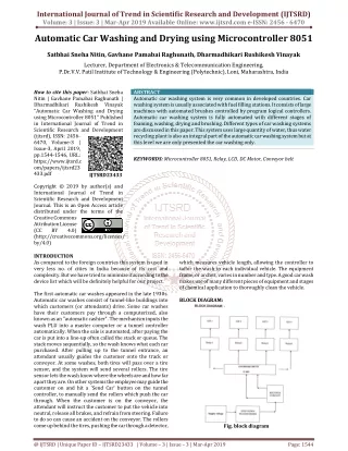
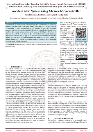
This paper is of great importance for monitoring and controlling the distance between the car and obstacles on the road. The objective of this paper was to monitor and control automatically the vehicle and to reduce many accidents. It is sure that this system will be able to save for human. This system mainly consists of the PIC 16F887A, temperature sensor DHT 11 , ultrasonic sensors HC SR04 , gas sensor MQ 2 , 20x4 LCD display, motors DC and motor driver L298N . The ultrasonic sensors are used to sense the distance for vehicle state information, which will continuously track for any obstacle from four sides of the car. The temperature changing from overheat of the car engine is monitored by using the temperature and humidity sensor. This system uses the gas sensor which will detect the smoke released by the heating car engine. The PIC 16F887A is used as a controller to control the direction of car. Moreover, if the vehicle detects the obstacles, this system displayed the distance between the car and obstacles on LCD and the safety alarm system contains by using a buzzer. Lae Yin Mon | Ni Ni San Hlaing "Automatic Monitoring and Controlling System for Vehicles using PIC Microcontroller" Published in International Journal of Trend in Scientific Research and Development (ijtsrd), ISSN: 2456-6470, Volume-3 | Issue-5 , August 2019, URL: https://www.ijtsrd.com/papers/ijtsrd26499.pdf Paper URL: https://www.ijtsrd.com/engineering/electronics-and-communication-engineering/26499/automatic-monitoring-and-controlling-system-for-vehicles-using-pic-microcontroller/lae-yin-mon<br>

E N D
International Journal of Trend in Scientific Research and Development (IJTSRD) Volume 3 Issue 5, August 2019 Available Online: www.ijtsrd.com e-ISSN: 2456 – 6470 Automatic Monitoring and Controlling System for Vehicles using PIC Microcontroller Lae Yin Mon, Ni Ni San Hlaing Department of Electronic Engineering, Technological University, Kyaukse, Myanmar How to cite this paper: Lae Yin Mon | Ni Ni San Hlaing "Automatic Monitoring and Controlling System for Vehicles using PIC Microcontroller" Published in International Journal of Trend in Scientific Research and Development (ijtsrd), ISSN: 2456- 6470, Volume-3 | Issue-5, August 2019, pp.783-786, https://doi.org/10.31142/ijtsrd26499 Copyright © 2019 by author(s) and International Journal of Trend in Scientific Research and Development Journal. This is an Open Access article distributed under the terms of the Creative Commons Attribution License (CC BY 4.0) (http://creativecommons.org/licenses/by /4.0) I. INTRODUCTION There are many kinds of advanced technology for vehicle safety. The reason for many accidents have been caused is due to sloppy drivers when driving cars Therefore, many advanced technologies are invited to reduce accidents all over the world. This system can be widely used in the fields of transporting environments. Sensors are so plentiful and widespread that they are commonly taken for granted. Sensors and microcontrollers have been integrated for specific applications. The project aims in designing a system which can automatically control the direction of the car on roads and also monitor the temperature changing from overheat of the car engine. This system is designed using two PIC microcontroller, LCD and buzzer. The microcontroller controls the motor driver to move the direction of robot car left or right and forward, backward. Three kinds of sensors are added in this system. These sensors are ultrasonic sensor, temperature and humidity sensor and gas sensor. The ultrasonic sensor estimates the distance between the car and an object. This system uses four ultrasonic sensors. They are set up at four sides of the car. If an object is very closer to the car and over the limit, the car will stop. The temperature and humidity sensor is used to measure the heat of the car engine. The gas sensor is used to sense the smoke released by the heating car engine. The buzzer is used for the alarm system. This automatic monitoring and controlling system are to be safe for vehicle. ABSTRACT This paper is of great importance for monitoring and controlling the distance between the car and obstacles on the road. The objective of this paper was to monitor and control automatically the vehicle and to reduce many accidents. It is sure that this system will be able to save for human. This system mainly consists of the PIC 16F887A, temperature sensor (DHT-11), ultrasonic sensors (HC-SR04), gas sensor (MQ-2), 20x4 LCD display, motors (DC) and motor driver (L298N). The ultrasonic sensors are used to sense the distance for vehicle state information, which will continuously track for any obstacle from four sides of the car. The temperature changing from overheat of the car engine is monitored by using the temperature and humidity sensor. This system uses the gas sensor which will detect the smoke released by the heating car engine. The PIC 16F887A is used as a controller to control the direction of car. Moreover, if the vehicle detects the obstacles, this system displayed the distance between the car and obstacles on LCD and the safety alarm system contains by using a buzzer. KEYWORDS: control, gas sensor, PIC 16F887A microcontroller, temperature sensor, ultrasonic sensors IJTSRD26499 II. Automatic monitoring and controlling system are mainly designed an automatically monitor and control the individual vehicle moving on the road. This system is based on PIC 16F887A microcontroller. The robot car needs a mechanical arrangement of the chassis, four wheels robotic vehicle with a caster wheel is constructed on the robot facing towards. The motion of the four motors of the robot car is entirely controlled by PIC microcontroller. In-vehicle monitor system, ultrasonic sensors are fixed at four sides of the car. The system operation is forward, backward, left and right direction of robot car by rotating four DC motor attached with four wheels. The motion of the robot car depends on sensing of ultrasonic sensors. The sensors send their sensing values to the microcontroller for converting analog input values to digital output values. The block diagram of this system and design aspect of independent modules is considered. DESIGN AND IMPLEMENTATION OF THE SYSTEM @ IJTSRD | Unique Paper ID – IJTSRD26499 | Volume – 3 | Issue – 5 | July - August 2019 Page 783
International Journal of Trend in Scientific Research and Development (IJTSRD) @ www.ijtsrd.com eISSN: 2456-6470 Figure3. Circuit Diagram of the System (Temperature and Gas sensor) IV. FLOW CHART OF THE SYSTEM Flow chart of the ultrasonic sensors is shown in figure4. Firstly, it initializes the input/output pins of the device. The ultrasonic sensor1 detects any obstacles. If there is no object, the robot car goes forward direction. On the contrary, if an object exists, that the distance is less than the limited distance, ultrasonic sensor2 and sensor3 detect an object. So, if an object exists, the left distance is less than the right distance, turn right. If not, turn left. If both sides are less than the limited distance, sensor4 detects an object. If the distance is less than the limited distance, goes backward. If not, stop the motor. Figure1. Block Diagram of the System The temperature and humidity sensor is used to sense the value of temperature for the car engine. If the temperature of the car engine increases and is greater than limited temperature, the fan attached to the car engine operates to decrease the engine heat. The temperature and humidity value are displayed on LCD. The gas sensor is used to detect the smoke which exhausts from the heating car engine. If the smoke is greater than the limited value, and then the buzzer will ring and immediately the car will stop. The gas value in the car engine exhaust is shown as a warning message on LCD. 12V battery is used for power supply. The overall block diagram is shown in figure1. III. CIRCUIT DESIGN OF THE SYSTEM This circuit consists of PIC 16F887A microcontroller, four ultrasonic sensors, fours motors and motor driver circuit. The circuit diagram of the system using ultrasonic sensors is shown in figure2. Figure2. Circuit Diagram of the System (Ultrasonic sensor) The circuit diagram of the system using temperature and gas sensors is shown in figure3. This circuit consists of PIC 16F887A microcontroller, fun, and buzzer. Figure4. Flow Chart of the ultrasonic sensor @ IJTSRD | Unique Paper ID – IJTSRD26499 | Volume – 3 | Issue – 5 | July - August 2019 Page 784
International Journal of Trend in Scientific Research and Development (IJTSRD) @ www.ijtsrd.com eISSN: 2456-6470 Figure7. Displaying Temperature and Humidity Data on LCD The results of the temperature, humidity and smoke sensor are shown in Figure8. For this task, the smoke sensor will firstly sense the ambient smoke which exhausts from the heating car engine and displays the smoke on the LCD screen. Figure5. Flow Chart of the Temperature and Gas Sensor Figure5 shows the flow chart of the temperature and gas sensor. The temperature and humidity sensor is used for sensing the heat of the car engine. The gas sensor is used to detect the smoke released by the heating car engine. Firstly, it initializes the input/output pins of the device. If the temperature value is greater than the limited temperature (80C), the fan will be on. Unless the temperature rises the limited value, the fun is off. And then the gas sensor senses the smoke. If the smoke is greater than the limited gas value which the heating car engine, the buzzer will alarm and immediately the motor will stop. If not, run the motor. V. TEST AND RESULT This system was designed and tested. In this section, testing results of the system are shown that is the direction of a robot car, forward, left and right and back. The following results are the forward direction of the robot car. Figure6 shows the robot car turn to the forward direction. Figure8. Displaying Temperature, Humidity and Smoke Data on LCD The following results are the left direction of the robot car. The robot car can detect any obstacle using ultrasonic sensor connected to the PIC microcontroller. If an object exists in front of the car, the left distance is less than right distance, turn right. If not, turn left. The robot car turns to the left is shown in figure9. Figure9. Left Direction of the Robot Car The robot moving backward direction is shown in figure10. The robot car detects any obstacle in surroundings using the ultrasonic sensor. If the car exists in the surrounding obstacles and within the limited distance, go back on the road. The following results are the back direction of the robot car. Figure6. Forward Direction of the Robot Car A 2 row by 16 column LCD screen was used for displaying the sense data. This LCD screen was attached to the PIC16F887 microprocessor. Figure7 shows the results of the temperature and humidity sensor. @ IJTSRD | Unique Paper ID – IJTSRD26499 | Volume – 3 | Issue – 5 | July - August 2019 Page 785
International Journal of Trend in Scientific Research and Development (IJTSRD) @ www.ijtsrd.com eISSN: 2456-6470 engine. The fun attached to the car engine was operated to reduce the engine heat when the engine temperature is greater than the limited value. The value of the temperature, humidity, and smoke was showed on the LCD display. And also the direction of the robot car was displayed on the LCD screen. The buzzer was used for a safety alarm system. As a conclusion, the prototype designed in this paper can give to the vehicle saving and reduce the accidents. REFERENCES [1]Microchip Technology Inc. DS39582B: PIC 16FXX Data Sheet, https://www.microchip.com [2]30 projects using PIC BASIC and BASIC PRO, Dogan Ibrahim, https://books.elsevier.com Figure10. Backward Direction of the Robot Car [3]Persi.TP, Microcontroller Based Vehicle Monitoring System using Controller Area Network Protocol”. “Design and Development of PIC Robot car moves according to the working principle and the system operation is repeated by sensing signal of ultrasonic sensors. VI. CONCLUSION Automatic monitoring and controlling system for vehicles were designed in this paper. This design was based on two PIC16F887A microcontrollers. The directions of the robot car were controlled by PIC microcontroller. The vehicle monitoring system was detected using four ultrasonic sensors which attached four sides of the car. The gas sensor was used to detect the smoke released by the heating car [4]https://pic-microcontroller.com/pic-16f877-based- projects [5]S. Menage,” Vehicle Automation and Accident Avoidance by Detecting Pedestrian Using Multiple Sensors”, IJARBEST, Vol.2, March 2016. [6]MQ-2 Gas Sensor Pinout, Feature, Equivalents & Data Sheet, https://components 101.com/mq2-gas-sensor [7]LCD 2×16 Pinout, Feature, Discription & Data Sheet, https://components 101.com/mq2-gas-sensor @ IJTSRD | Unique Paper ID – IJTSRD26499 | Volume – 3 | Issue – 5 | July - August 2019 Page 786