Download
1 / 17
170 likes | 300 Vues
Explore the impact of break length, tuning, and phase adjustment on the performance of the LCLS undulator system, focusing on amplitude, energy change, and phase correction strategies.

E N D
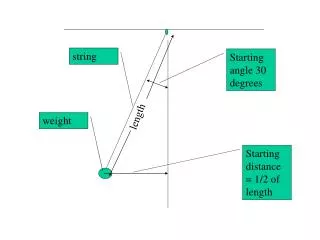
Break Length Tuning and Phase Adjustment I. Vasserman LCLS UNDULATOR SYSTEM MEETING June 29, 2004
Outline • Break length correctionat regular part: Phase shims, pole gap change, trajectory shims, Keff • Phase correction at saturation Complex amplitude vs. distortions • One device removed • Summary Argonne June 29, 2004
Breake length change vs. phase shim number 0.2 mm thick phase shims at one end (magnets from 7 to 2) Argonne June 29, 2004
Phase Shims Signature Phase shims 0.2 mm thick applied to 12 magnets at U/S end Argonne June 29, 2004
Complex amplitude and phase • Complex amplitude of radiation and phase slippage are defined below Complex amplitude of radiation Phase slippage over the length of one section Intensity of radiation is defined by |A|2 Argonne June 29, 2004
Break length definition • Lf = nu(1+K2eff /2) -> required length in free space: • Tolerance for phase error between sections ~10 Supposed tapering required after saturation at last 30 m of undulator to compensate for particle energy loss 0.4%: corresponds to 2.5° of phase error for break section with n=1, or 7.5° with n=3 Argonne June 29, 2004
|A| vs. arg(A) for two devices in row n=3 LCLS prototype. Close to 100% performance. |A| is equal to length of the vector at plot Argonne June 29, 2004
Energy changed by 0.4% Worst case with biggest energy loss and long break is chosen Performance is close to zero, very sensitive to the energy change. Argonne June 29, 2004
0.4% Energy change. Keff corrected Performance is 97.5%. Close to requirements with no break length correction Argonne June 29, 2004
Full correction of Keff to compensate for phase Performance is 99.2%, close to perfect. No break length correction Argonne June 29, 2004
Discussion • Recent 3 mrad cant requires ~8mm shift in X to obtain change in Keff for compensation of 0.4% change in energy. A possible option is to shift devices at saturation area in X to –4 mm in advance to allow then going full way up to 4 mm to cover all range of energy change. Additional tuning for such devices could be necessary to provide proper performance in wide X-range • Possibility to remove one device during commissioning was investigated. For recent design with Keff=3.63 Ld/Lf=16.08 Such distorrtion could be corrected by changing the Keff; for Keff=3.44 (gap 6.9 mm) Ld/Lf=16.54. It means that this option requires a phase shifter to adjust the phase after removing the device Argonne June 29, 2004
One device removed, Keff corrected (k=3.636*0.9996) 0.08 phase distortion compensated by 0.0004 change of K/K (0.8mm shift in X), 99.3% performance Argonne June 29, 2004
Same as before for K=3.44 0.4 phase distortion compensated by 0.0016 change of K/K (3.2 mm shift in X), 81.6% performance Argonne June 29, 2004
Summary Initial tuning • If phase between devices too big: Phase shims must be applied to correct the break length; • If phase between devices too small: gap for end poles must be decreased. This option is undesirable, and initial break length should be defined with part of phase shims already in place to allow tuning of the break length in both directions without affecting the gap; • Other possibilities could be chosen as well if necessary (Keff correction, trajectory shims) Argonne June 29, 2004
Summary (Cont) • Main reason for Keff variation desirability is particle energy change at saturation stage; • By adjusting the Keff proper performance could be easily restored. Performance is extremely sensitive to Keff . Even in case of tuning in advance the devices to the proper Keff ,remote control of it is absolutely necessary during commissioning, taking into account uncertainty in beam energy loss at saturation; • Another source of concern for Keff stability is temperature variation. Two possible solutions are: remote X-position control to compensate for temperature change and/or temperature stabilization of the whole tunnel. Each section must have at least 2 temperature sensors at U/S and D/S end of the device and this temperature must be stable within ±0.2°C. Could it be achieved by tunnel temperature control only remains doubtful. Argonne June 29, 2004
Summary (Cont) • Main conclusion from here: no active correction of phase between devices is necessary Keff tuning is crucial and remote control of X-position is necessary option with Keff =3.44 requires phase shifter to work with one device removed Argonne June 29, 2004