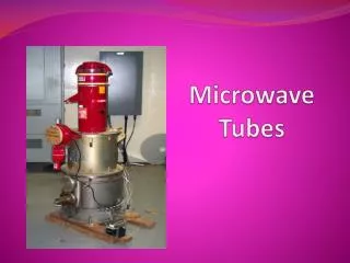
Conventional Tubes
Conventional Tubes. Conventional Device tubes cannot be used for frequencies above 100MHz 1. Interelectrode capacitance 2. Lead Inductance effect 3. Transit time effect 4. Gain Bandwidth limitation 5. Effect of RF losses (Conductance, dielectric) 6. Effect due to radiation losses.

Conventional Tubes
E N D
Presentation Transcript
Conventional Tubes • Conventional Device tubes cannot be used for frequencies above 100MHz • 1. Interelectrode capacitance • 2. Lead Inductance effect • 3. Transit time effect • 4. Gain Bandwidth limitation • 5. Effect of RF losses (Conductance, dielectric) • 6. Effect due to radiation losses
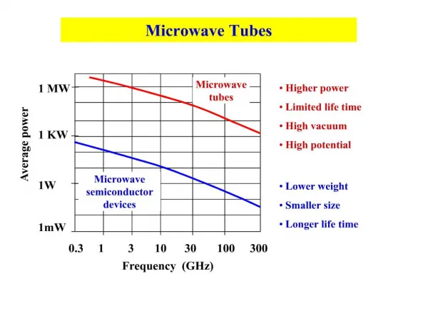
Efficient Microwave tubes usually operate on the theory of electron velocity modulation concept • The electron transit time is used in the conversion of dc power to RF power
Linear Beam O tubes • The paramount O – type tube is the two cavity klystron followed by the reflex klystron. • Slow wave structures are also O-type but have non-resonant periodic structures for electron interactions. • Twystron is a hybrid amplifier which uses a combination of klystron and Slow wave structures. s
KLYSTRON • There are two basic configurations of klystron tubes • 1. Reflex Klystron used as a low-power Microwave oscillator • 2. Multi cavity klystron used as low-power microwave amplifier
REFLEX KLYSTRON • Single Re-entrant cavity as a resonator. • The electron beam emitted from the cathode is accelerated by the grid and passes through the cavity anode to the repeller space between the cavity anode and the repeller electrode . • The feedback required to maintain the oscillations within the cavity is obtained by reversing electron beam emitted from the cathode towards repeller electrode and sending it back through the cavity.
The electrons in the beam are velocity modulated before the beam passes through the cavity thesecond time and give up the energy to the cavity to maintain oscillations. • This type of a Klystron is called a Reflex Klystron because of the reflex action of the electron beam.
REENTRANT CAVITY • Therefore the reentrant cavities are designed for use in klystron and microwave triodes • A reentrant cavity is one in which the metallic boundaries extend into the interior of the cavity • Inductance decreased • Reduced resistance losses • Prevents radiation losses
Mechanism of Oscillation • It is assumed that the oscillations are set up in the tube initially due to noise or switching transients and the oscillations are sustained by device operation. • The electrons passing through the cavity gap d experience this RF field and are velocity modulated.
Applegate diagram • The electrons B which encountered the positive half cycle of the RF field in the cavity gap d will be accelerated, A which encountered zero RF field will pass with unchanged original velocity, and c which encountered the negative half cycle will be retarded on entering the repeller space. • All these velocity modulated electrons will be repelled back to the cavity by the repeller due to the negative potential.
The repeller distance L and the voltages can be adjusted to receive all the electrons at a same time on the positive peak of the cavity RF velocity cycle. • Thus the velocity modulated electrons are bunched together and lose their kinetic energy when they encounter the positive cycle of the cavity RF field.
Bunches occur once per cycle centered around the reference electron and these bunches transfer maximum energy to the gap to get sustained oscillations. • For oscillations to be sustained, the time taken by the electrons to travel into the repeller space and back to the gap (transit time) must have an optimum value.
Mode of Oscillation • The electrons should return after 1¾, 2 ¾ or 3 ¾ cycles – most optimum departure time. • If T is the time period at the resonant frequency, to is the time taken by the reference electron to travel in the repeller space between entering the repeller space and returning to the cavity at positive peak voltage on formation of the bunch Then, to = (n + ¾)T = NT Where N = n + ¾, n = 0,1,2,3……. N – mode of oscillation.
The mode of oscillation is named as N = ¾, 1 ¾ 2 ¾ etc for modes n = 0,1,2……resp. The Power output of lowest mode?
Principle • Velocity modulated tube • High velocity electron beam is generated by an electron gun and sent down along a gas tube through an input cavity (BUNCHER), drift space (FIELD FREE) and an output cavity (CATCHER) to a collector electrode anode. • The anode is kept positive to receive the electrons, while the output is taken from the tube via resonant cavities with the aid of coupling loops
Two grids of the buncher cavity are separated by a small gap A while the two grids of the catcher cavity are separated by a small gap B.
OPERATION • The input buncher cavity is exited by the RF signal, (the signal to be amplified) which will produce an alternating voltage of signal frequency across the gap A. • This voltage generated at the gap A is responsible to produce bunching of electrons or velocity modulation of the electron beam.
HISTORY • The brothers Russell and Sigurd Varian of Stanford University are the inventors of the klystron. Their prototype was completed in August 1937.
Reentrant Cavity • At a frequency well below the microwave range, the cavity resonator can be represented by a lumped-constant resonant circuit. • When the operating frequency is increased to microwave range, both the inductance and capacitance must be reduced to a minimum in order to maintain resonance at the operating frequency. • Ultimately the inductance is reduced to a minimum by short wire.