Download
1 / 41
530 likes | 1.92k Vues
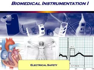
Biomedical Instrumentation I. Electrical Safety. This Week. Safety in the clinical environment: Electrical safety Physiological effects of electricity Susceptibility parameters Distribution of electrical power Isolated power systems Macroshock hazards Microshock hazards

E N D
Biomedical Instrumentation I Electrical Safety
This Week • Safety in the clinical environment: Electrical safety • Physiological effects of electricity • Susceptibility parameters • Distribution of electrical power • Isolated power systems • Macroshock hazards • Microshock hazards • Electrical safety codes and standards • Protection • Power distribution • Ground fault circuit interrupters (GFCI) • Equipment design • Electrical safety analyzers / Testing electrical systems
Safety in Clinical Environment • Electrical hazards • Electrical shocks (micro and macro) due to equipment failure, failure of power delivery systems, ground failures, burns, fire, etc. • Mechanical hazards • mobility aids, transfer devices, prosthetic devices, mechanical assist devices, patient support devices • Environmental hazards • Solid wastes, noise, utilities (natural gas), building structures, etc. • Biological hazards • Infection control, viral outbreak, isolation, decontamination, sterilization, waste disposal issues • Radiation hazards • Use of radioactive materials, radiation devices (MRI, CT, PET), exposure control
Electrical Safety • Many sources of energy, potentially hazardous substances, instruments and procedures • Use of fire, compressed air, water, chemicals, drugs, microorganisms, waste, sound, electricity, radiation, natural and unnatural disaster, negligence, sources of radiation, etc. • Medical procedures expose patients to increased risks of hazards due to skin and membranes being penetrated / altered • 10,000 device related injuries in the US every year! Typically due to • Improper use • Inadequate training • Lack of experience • Improper (lack of) use of manuals • Device failure
Physiological Effects of Electricity • For electricity to have an effect on the human body: • An electrical potential difference must be present • The individual must be part of the electrical circuit, that is, a current must enter the body at one point and leave it at another. • However, what causes the physiological effect is NOT voltage, but rather CURRENT. • A high voltage (KV,(103V)) applied over a large impedance (rough skin) may not cause much (any) damage • A low voltage applied over very small impedances (heart tissue) may cause grave consequences (ventricular fibrillation) • The magnitude of the current is simply the applied voltage divided by the total effective impedance the current faces; skin : largest. • Electricity can have one of three effects: • Electrical stimulation of excitable tissue (muscles, nerve) • Resistive heating of tissue • Electrical burns / tissue damage for direct current and high voltages
Physiological Effects of Electricity The real physiological effect depends on the actual path of the current Dry skin impedance:93 kΩ / cm2 Electrode gel on skin: 10.8 kΩ / cm2 Penetrated skin: 200 Ω / cm2 Physiological effects of electricity. Threshold or estimated mean values are given for each effect in a 70 kg human for a 1 to 3 s exposure to 60 Hz current applied via copper wires grasped by the hands.
Physiological Effects of Electricity • Threshold of perception: The minimal current that an individual can detect. For AC (with wet hands) can be as small as 0.5 mA at 60 Hz. For DC, 2 ~10 mA • Let-go current: The maximal current at which the subject can voluntarily withdraw. 6 ~ 100 mA, at which involuntary muscle contractions, reflex withdrawals, secondary physical effects (falling, hitting head) may also occur • Respiratory Paralysis / Pain / Fatigue At as low as 20 mA, involuntary contractions of respiratory muscles can cause asphyxiation / respiratory arrest, if the current is not interrupted. Strong involuntary contraction of other muscles can cause pain and fatigue • Ventricular fibrillation 75 ~ 400 mA can cause heart muscles to contract uncontrollably, altering the normal propagation of the electrical activity of the heart. HR can raise up to 300 bpm, rapid, disorganized and too high to pump any meaningful amount of blood ventricular fibrillation. Normal rhythm can only return using a defibrillator • Sustained myocardial contraction / Burns and physical injury At 1 ~6 A, the entire heart muscle contracts and heart stops beating. This will not cause irreversible tissue damage, however, as normal rhythm will return once the current is removed. At or after 10A, however, burns can occur, particularly at points of entry and exit.
Important Susceptibility Parameters • Threshold and let-go current variability Distributions of perception thresholds and let-go currents These data depend on surface area of contact, moistened hand grasping AWG No. 8 copper wire, 70 kg human, 60Hz, 1~3 s. of exposure
Important Susceptibility Parameters • Frequency • Note that the minimal let-go current happens at the precise frequency of commercial power-line, 50-60Hz. • Let-go current rises below 10 Hz and above several hundred Hz. Let-go current versus frequency Percentile values indicate variability of let-go current among individuals. Let-go currents for women are about two-thirds the values for men.
Important Susceptibility Parameters • Duration • The longer the duration, the smaller the current at which ventricular fibrillation occurs • Shock must occur long enough to coincide with the most vulnerable period occurring during the T wave. • Weight • Fibrillation threshold increases with body weight (from 50mA for 6kg dogs to 130 mA for 24 kg dogs. Fibrillation current versus shock duration.Thresholds for ventricular fibrillation in animals for 60 Hz AC current. Duration of current (0.2 to 5 s) and weight of animal body were varied.
Important Susceptibility Parameters • Points of entry • The magnitude of the current required to fibrillate the heart is far greater if the current is applied directly to heart; externally applied current loses much of its amplitude due to current distributions. Large, externally applied currents cause macroshock. • If catheters are used, the natural protection provided by the skin 15 kΩ ~ 2 MΩ) is bypassed, greatly reducing the amount of current req’d to cause fibrillation. Even smallest currents (80 ~ 600 μA), causing microshock, may result in fibrillation. Safety limit for microshocks is 10 μA. • The precise point of entry, even externally is very important: If both points of entry and exit are on the same extremity, the risk of fibrillation is greatly reduced even at high currents (e.g. the current req’d for fibrillation through Lead I (LA-RA) electrodes is higher than for Leads II (LL-RA) and III (LL-LA).
Important Susceptibility Parameters • Points of entry Effect of entry points on current distribution(a) Macroshock, externally applied current spreads through-out the body. (b) Microshock, all the current applied through an intracardiac catheter flows through the heart.
Distribution of Electrical Power (230 V) Simplified electric-power distribution for 115 V circuits. Power frequency is 60 Hz
Distribution of Power • If electrical devices were perfect, only two wires would be adequate (hot and return), with all power confined to these two wires. However, there are two major departures from this ideal case: • A fault may occur, through miswiring, component failure, etc., causing an electrical potential between an exposed surface (metal casing of the device) and a grounded surface (wet floor, metal case of another device etc.) Any person who bridges these two surfaces is subject to macroshock. • Even if a fault does not occur, imperfect insulation or electromagnetic coupling (capacitive or inductive) may produce an electrical potential relative to the ground. A susceptible patient providing a path for this leakage current to flow to the ground is subject to microshock. • The additional ground line provides a good line of defense! (how / why?)
GROUND! • The additional line that is connected directly to the earth-ground provides the following: • In case of a fault (short circuit between hot conductor and metal casing), a large current will use the path through the ground wire (instead of the patient) and not only protect the patient, but also cause the circuit breaker to open. The ability of the grounding system to conduct high currents to ground is crucial for this to work! • If there is no fault, the ground wire serves to conduct the leakage current safely back to the electrical power source – again, as long as the grounding system provides a low-resistance pathway to the ground • Leakage current recommended by ECRI are established to prevent injury in case the grounding system fails and a patient touches an electrically active surface (10 ~ 100 μA).
Isolated Power Distribution Not grounded ! • In fact, in such an isolated system, if a single ground-fault occurs, the system simply reverts back to the normal ground-referenced system. • A line isolation monitor is used with such system that continuously monitors for the first ground fault, during which case it simply informs the operators to fix the problem. The single ground fault does NOT constitute a hazard! • Normally, when there is a ground-fault from hot wire to ground, a large current is drawn causing a potential hazard, as the device will stop functioning when the circuit breakers open ! • This can be prevented by using the isolated system, which separates ground from neutral, making neutral and hot electrically identical. A single ground-fault will not cause large currents, as long as both hot conductors are initially isolated from ground!
Macroshock • Most electrical devices have a metal cabinet, which constitutes a hazard, in case of an insulation failure or shortened component between the hot power lead and the chassis. There is then 115 ~ 230 V between the chassis and any other grounded object. • The first line of defense available to patients is their skin. • The outer layer provides 15 kΩ to 1 MΩ depending on the part of the body, moisture and sweat present, 1% of that of dry skin if skin is broken, • Internal resistance of the body is 200Ω for each limb, and 100Ω for the trunk, thus internal body resistance between any two limbs is about 500Ω (somewhat higher for obese people due to high resistivity of the adipose tissue)! • Any procedure that reduces or eliminates the skin resistance increases the risk of electrical shock, including biopotential electrode gel, electronic thermometers placed in ears, mouth, rectum, intravenous catheters, etc. • A third wire, grounded to earth, can greatly reduce the effect of macroshock, as the resistance of that path would be much smaller then even that of internal body resistance!
Macroshock Hazards • Direct faults between the hot conductor and the ground is not common, and technically speaking, ground connection is not necessary during normal operation. • In fact, a ground fault will not be detected during normal operation of the device, only when someone touches it, the hazard becomes known. Therefore, ground wire in devices and receptacles must be periodically tested.
Microshock Hazards Small currents inevitably flow between adjacent insulated conductors at different potentials leakage currents which flow through stray capacitances, insulation, dust and moisture Leakage current flowing to the chassis flows safely to the ground, if a low-resistance ground wire is available.
Microshock Hazards • If ground wire is broken, the chassis potential rises above the ground; a patient who has a grounded connection to the heart (e.g. through a catheter) receives a microshock if s/he touches the chassis. • If there is a connection from the chassis to the patient’s heart, and a connection to the ground anywhere in the body, this also causes microshock. • Note that the hazard for microshock only exists if there is a direct connection to the heart. Otherwise, even the internal resistance of the body is high enough top prevent the microshocks.
Microshock via Ground Potentials Microshocks can also occur if different devices are not at the exact same ground potential. In fact, the microshock can occur even when a device that does not connected to the patient has a ground fault! A fairly common ground wire resistance of 0.1Ω can easily cause a a 500mVpotential difference if initiated due to a, say 5A of ground fault. If the patient resistance is lessthen 50kΩ, this would cause an above safe current of 10μA
Safety Codes & Standards • Limits on leakage current are instituted and regulated by the safety codes instituted in part by the National Fire Protection Association (NFPA), American National Standards Institute (ANSI), Association for the Advancement of Medical Instrumentation (AAMI), and Emergency Care Research Institute (ECRI).
Basic Approaches to Shock Protection • There are two major ways to protect patients from shocks: • Completely isolate and insulate patient from all sources of electric current • Keep all conductive surfaces within reach of the patient at the same voltage • Neither can be fully achieved some combination of these two • Grounding system • Isolated power-distribution system • Ground-fault circuit interrupters (GFCI)
Grounding Systems • Low resistance (0.15 Ω) ground that can carry currents up to the circuit-breaker ratings protects patients by keeping all conductive surfaces and receptacle grounds at the same potential. • Protects patients from • Macroshocks • Microshocks • Ground faults elsewhere (!) • The difference between the receptacle grounds and other surface should be no more then 40 mV) All the receptacle grounds and conductive surfaces in the vicinity of the patient are connected to the patient-equipment grounding point. Each patient-equipment grounding point is connected to the reference grounding point that makes a single connection to the building ground.
Isolated Power Systems • A good equipotential grounding system cannot eliminate large current that may result from major ground-faults (which are rather rare). • Isolated power systems can protect against such major (single) ground faults • Provide considerable protection against macroshocks, particularly around wet conditions • However, they are expensive ! • Used only at locations where flammable anesthetics are used. Additional minor protection against microshocks does not justify the high cost of these systems to be used everywhere in the clinical environment
Ground – Fault Circuit Interrupters (GFCI) • Disconnects source of electric current when a ground fault greater than about 6 mA occurs! When there is no fault, Ihot=Ineutral. The GFCI detects the difference between these two currents. If the difference is above a threshold, that means the rest of the current must be flowing through elsewhere, either the chassis or the patient !!!. The detection is done through the monitoring the voltage induced by the two coils (hot and neutral) in the differential transformer!
GFCI The National Electric Code (NEC - 1996) requires that all circuits serving bathrooms, garages, outdoor receptacles, swimming pools and construction sites be fitted with GFCI. Note that GFCI protect against major ground faults only, not against microshocks. Patient care areas are typically not fitted with GFCI, since the loss of power to life support equipment can also be equally deadly!
Protection through Equipment Design • Strain-relief devices for cords, where cord enters the equipment and between the cord and plug • Reduction of leakage current through proper layout and insulation to minimize the capacitance between all hot conductors and the chassis • Double insulation to prevent the contact of the patient with the chassis or any other conducting surface (outer case being insulating material, plastic knobs, etc.) • Operation at low voltages; solid state devices operating at <10V are far less likely to cause macroshocks • Electrical isolation in circuit design
Isolation barrier ISO RF CM Error Error CMRR IMRR* ~ ~ - - ~ SIG ISO + + Isolation Capacitance and resistance CM ~ ~ Input common Output o CM ISO ISO = SIG ± ± Gain common CMRR IMRR (a) *IMRR in v/v Electrical Isolation • Main features of an isolation amplifier: • High ohmic isolation between input and output (>10MΩ) • High isolation mode voltage (>1000V) • High common mode rejection ration (>100 dB)
FB AD202 Signal - Demod Hi In - Mod In + + ± 5 V F.S. ± 5 V o SIG F.S. Lo In com Power +ISO Out Rect and filter + 7.5 V Oscillator + 15 V DC • ISO • Out - 7.5 V 25 kHz 25 kHz Power return (b) Transformer Isolation Amplifiers
Isolation barrier RK= 1M W CR3 CR1 CR2 i i2 i 1 2 +V +o RG - - i2 AI AII i1 + + + + i3 i ~ o - -V - Input control RK Output o = i control RG (c) Optical Isolation Amplifier
Electrical Safety AnalyzersWiring / Receptacle Testing • Three LED receptacle tester: • Simple device used to test common wiring problems (can detect only 8 of possible 64 states) • Will not detect ground/neutral reversal, or when ground/neutral are hot and hot is grounded (GFCI would detect the latter)
Electrical Safety AnalyzersTesting Electrical Appliances • Ground-pin-to-chassis resistance: Should be <0.15Ω during the life of the appliance Ground-pin-to-chassis resistance test
Electrical Safety AnalyzersTesting Electrical Appliances • Chassis leakage current: The leakage current should not exceed 500μA with single fault for devices not intended for patient contact, and not exceed 300 μA for those that are intended for patient contact. Appliance power switch (use both OFF and ON positions) Open switch for appliances not intended to contact a patient Grounding-contact switch (use in OPEN position) Polarity- reversing switch (use both positions) Appliance H (black) To exposed conductive H surface or if none, then 10 by Internal Circuitry N 120 V 20 cm metal foil in contact N (white) with the exposed surface G Insulating surface G (green) I H = hot Building ground Current meter N = neutral (grounded) G = grounding conductor Test circuit This connection is at service I < 500 μA for facility Ð owned housekeeping and maintenance appliances entrance or on I > 300 μA for appliances intended for use in the patient vicinity supply side of separately derived system
Electrical Safety AnalyzersTesting Electrical Appliances • Leakage current in patient leads: • Potentially most damaging leakage is the one with patient leads, since they typically have low impedance patient contacts • Current should be restricted to 50μA for non-isolated leads and to 10 μA for isolated leads (used with catheters / electrodes that make connection to the heart) • Leakage current between any pair of leads, or between a single lead and other patient connections should also be controlled • Leakage in case of line voltage appearing on the patient should also be restricted.
Leakage current Testers Test for leakage current from patient leads to ground
Leakage Current testers Test for leakage current between patient leads
Leakage Current Testers Test for ac isolation current Isolation current is the current that passes through patient leads to ground if and when line voltage appears on the patient. This should also be limited to 50μA