Download
1 / 14
140 likes | 285 Vues
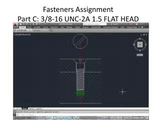
This document provides a detailed guide for designing a fastener with a 3/8-16 UNC thread and flat head. It includes instructions on drawing a vertical rectangle and mirroring an angled line. Key dimensions such as 1/4D for height and width are referenced, along with guidance on creating a clearance hole in the top plate and a tapped bottom plate with extended threads. Additionally, it explains the importance of a pilot hole and its angle, ensuring robust fastener installation. Refer to the included PDF for critical dimensions and visual references.

E N D
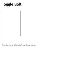
Check PDF packet page one for quick reference to page numbers… Start by drawing the following vertical rectangle .375x1.5
Offset top line down ½ D (0.1875) • Draw a line from the blue circle intersection heading “@1<50” • Mirror angled line over to the left side of the fastener and fillet, trim, extend, / erase.
Add slot for screw driver. Dimensions for height and width are 1/4D as noted in the book example.
Check last page of PDF for dimensions of steel plates. • Top plate has a clearance hole for the fastener. • Bottom plate is tapped (threaded)- See page 1 of PDF for page number referencing threaded holes • Bottom plate has more threads cut than length of bolt, i.e. bolt can’t bottom out without fully tightening down. • Pilot hole (pre-drilled hole before tapping can occur) extends lower than threads and has 80 degree angle (same as the twist drill bit that cut the hole). Dimensions can be “eye balled.”