Manual Process Planning
Manufacturing Processes (2), IE-352 Ahmed M El-Sherbeeny, PhD Spring 2015. Manual Process Planning. Chapter Outline. Introduction Manual Process Planning Process Plan Part Features Identification and Processes Selection Processes Sequencing. Introduction. Process Planning Known as:

Manual Process Planning
E N D
Presentation Transcript
Manufacturing Processes (2), IE-352 Ahmed M El-Sherbeeny, PhD Spring 2015 Manual Process Planning
Chapter Outline Introduction Manual Process Planning Process Plan Part Features Identification and Processes Selection Processes Sequencing
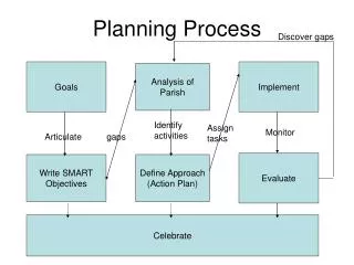
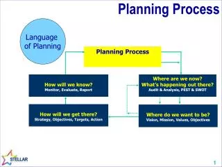
Introduction Process Planning Known as: manufacturing planning material processing process engineering machine routing Definition: act of preparing detailed work instructions to produce a part it’s a function within the manufacturing facility (see figure) establishes processes and parameters used to convert part from initial form to final form predetermined in an engineering drawing person who develops process plan: often called process planner
Introduction Functions included in process planning: Raw material preparation Processes selection Process sequencing Machining parameter selection Tool path planning Machine selection Fixture selection
Introduction Factors Affecting Process Plan Selection: Shape Tolerance Surface finish Size Material type Quantity Value of the product Urgency Manufacturing system itself Two approaches to carry out task of process planning: Manual Process Planning Computer Aided Process Planning (CAPP)
Manual Process Planning Process planner must have following knowledge: Ability to interpret an engineering drawing Familiarity with manufacturing processes and practice Familiarity with tooling and fixtures Know what resources are available in the shop Know how to use reference books (e.g. machinability data handbooks) Ability to do computations on machining time and cost Familiarity with raw materials
Manual Process Planning Some necessary steps to prepare a process plan Study overall shape of part identify features, all critical dimensions Thoroughly study the drawing; try to identify all manufacturing features and notes Determine best raw material shape to use if raw stock not given Identify datum surfaces; Use information on datum surfaces to determine the setups Select machines for each setup. Determine rough sequence of operations necessary to create all the features for each setup
Process Plan Process Plan AKA (among others): operation sheet route sheet operation planning summary Detailed plan contains: route processes process parameters machine and tool selections fixtures
Process Plan The level of details in the plan depends on the application: Operation: a process Operation Plan (Op-plan): description of an operation includes tools, machines to be used, process parameters, machining time, etc. Op-plan sequence: Summary of a process plan
Part Features Identification and Processes Selection A wide variety of manufacturing processes are used to produce a workpiece These processes can be classified as: Casting processes Forming and shaping processes Machining processes Joining processes Finishing processes
Part Features Identification and Processes Selection Machining processes Drilling drilling, countering, countersinking, deep-hole drilling, etc. Boring Tapping Milling face milling, end milling Turning facing, straight turning, taper turning, parting, etc. Threading
Part Features Identification and Processes Selection Features that must be considered in selecting machining processes include: part features required dimensional and geometric accuracy and tolerance required surface finish available resources, including NC machines and cutting tools cost
Part Features Identification and Processes Selection Part features: distinctive geometric form or shape to be produced from raw material it determines process type, tool types (shapes and size), machine requirements (3-, 4-, or 5-axis), and tool path Two types of part features Basic features simple forms/shapes that require only one machining operation include holes, slots, pockets, shoulders, profiles, and angles Compound features consist of two or more basic part features e.g. the combined result of two holes with different diameters
Part Features Identification and Processes Selection Example: Machining Processes Selection Select the machining processes for the part shown in the figure given in the next slide. Assume required dimensional accuracy and surface roughness are within process capability of drilling and milling operations. The four sides of the raw material have been pre-machined to required dimensions.
Part Features Identification and Processes Selection Example: Machining Processes Selection (cont.)
Part Features Identification and Processes Selection Example: Machining Processes Selection (cont.) Solution: Top flat surface Outer profile Three holes Recommended machining processes for features are Face-milling: the top surface Rough-milling: the outer profile Finish-milling: the outer profile Center-drilling: the three holes Drilling: the three holes
Processes Sequencing Sequence of operations determined by three considerations: Datum surfaces should be machined first if multiple work-holding setups required If possible, datum surfaces should be pre-machined in manually operated machine to facilitate workpiece locating and clamping In cases where 2 holding setups are required: rough datum surfaces are preprocessed in a manually operated machine then used as setup references to produce finished datum surfaces for the final work-holding this ensures the accuracy of the finished part
Processes Sequencing Sequence of operations determined by 3 considerations(cont.) Surfaces with larger area have precedence Larger surfaces tend to be more adaptable to disturbances resulting from machining operations Feature interference should be avoided. Feature interference occurs when machining of one feature destroys a requirement for the production of other features This happens when there is interaction or dependency between machining operations
Processes Sequencing:Example The figure shown in the next slide is a workpiece in which some features are interrelated. The workpiece has five basic features a through slot in side C two angle strips (strip 1, strip 2) two through holes on strip 1 that are perpendicular to side A compound features are two tapped holes perpendicular to strip 1 Develop the process sequence for producing the part.
Processes Sequencing:Example (cont.) Solution: The raw material is cut from a block stock with dimensions: 6.25 x 4.25 x 2.25 in Studying the part features reveals: 2 through holes on strip 1 interact with the formation of angle slot in side C interacts with the cutting of angle β Machining angle strip 1 first difficulty in drilling 2 holes 2 holes must be produced before angle strip 1 Likewise, making angle strip 2 first difficulty in setting up workpiece to produce the through slot the slot has to be machined before angle strip 2 is made
Processes Sequencing:Example (cont.) Recommended processes sequence is: Setup A for machining side B Setup B for: machining sides A and E also drilling two holes on Side A Setup C for: machining sides C and F also cutting the slot in side C Setup D for: cutting angle strip 1 drilling two tap holes and tapping the two holes. Setup E for cutting angle strip 2