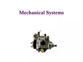
Mechanical Systems
Mechanical Systems. Translation Point mass concept P (t) = F(t)*v(t) Newton’s Laws & Free-body diagrams Rotation Rigid body concept P (t) = T(t)*w(t) Newton’s laws & Free-body diagrams Transducer devices and effects. Mechanical rotation. Newton’s Laws (applied to rotation)

Mechanical Systems
E N D
Presentation Transcript
Mechanical Systems • Translation • Point mass concept • P(t) = F(t)*v(t) • Newton’s Laws & Free-body diagrams • Rotation • Rigid body concept • P(t) = T(t)*w(t) • Newton’s laws & Free-body diagrams • Transducer devices and effects
Mechanical rotation • Newton’s Laws (applied to rotation) • Every body persists in a state of uniform (angular) motion, except insofar as it may be compelled by torque to change that state. • The time rate of change of angular momentum is equal to the torque producing it. • To every action there is an equal and opposite reaction. (Principia Philosophiae, 1686, Isaac Newton)
Quantities and SI Units • “F-L-T” system • Define F: force [N] • Define L: length [m] • Define T: time [s] • Derive • T: torque (moment) [N-m] • M: mass [kg] • w: angular velocity [rad/s] • J: mass moment of inertia [kg-m^2]
Physical effects and engineered components • Inertia effect - rigid body with mass in rotation • Compliance (torsional stiffness) effect – torsional spring • Dissipation (rotational friction) effect – torsionaldamper • System boundary conditions: • motion conditions – angular velocity specified • torque conditions - drivers and loads
Rotational inertia • Physical effect: r^2**dV • Engineered device: rigid body “mass” • Standard schematic icon (stylized picture) • Standard multiport representation • Standard icon equations
w 1 w T1 T2 I:J Rigid body in fixed-axis rotation: standard form J T1 T2
Compliance (torsional stiffness) • Physical effects: =E* • Engineered devices: torsional spring • Standard schematic icon • Standard multiport representation • Standard icon equations
0 C Torsional compliance w1 w2 T
Dissipation (torsional resistance) • Physical effects • Engineered devices: torsional damper • Standard schematic icons • Standard multiport representation • Standard icon equations
0 R Torsional resistance w1 w2 T
Free-body diagrams • Purpose: Develop a systematic method for generating the equations of a mechanical system. • Setup method: Separate the mechanical schematic into standard components and effects (icons); generate the equation(s) for each icon. • Standard form of equations: the composite of all component equations is the initial system set; select a reduced set of key variables (generalized coordinates); reduce the initial equation set to a set in these variables.
Multiport modeling of mechanical translation • Multiport representations of the standard icons: focus on power ports • Equations for the standard icons • Multiport modeling using the free-body approach
Multiport modeling of fixed-axis rotation based on free-body diagrams • Identify each rotating rigid body. • Define an inertial angular velocity for each. • Use a standard multiport component to represent each rotating rigid body (with or without mass). • Write the standard equation(s) for each component.