Download
1 / 108
1.08k likes | 1.18k Vues
Explore thermal management in FPGAs, measuring temperature, thermally driven adaptation, and experimental results. Discover temperature-safe real-time systems and future directions in FPGA technology.

E N D
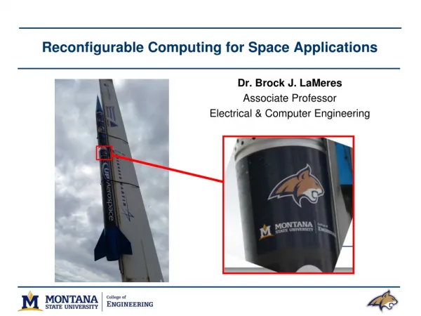
Adaptive Thermoregulation for Applications on Reconfigurable Devices Funded by NSF Grant ITR 0313203 Phillip Jones Applied Research Laboratory Washington University Saint Louis, Missouri, USA http://www.arl.wustl.edu/arl/~phjones Iowa State University Seminar April 2008
What are FPGAs? CLB CLB CLB CLB CLB CLB CLB CLB Configurable Logic Block CLB CLB CLB CLB CLB CLB CLB CLB • FPGA: Field Programmable Gate Array • Sea of general purpose logic gates
What are FPGAs? Configurable Logic Block • FPGA: Field Programmable Gate Array • Sea of general purpose logic gates CLB CLB CLB CLB CLB CLB CLB CLB CLB CLB CLB CLB CLB CLB CLB
What are FPGAs? Configurable Logic Block • FPGA: Field Programmable Gate Array • Sea of general purpose logic gates CLB CLB CLB CLB CLB CLB CLB CLB
FPGA Usage Models • Experimental ISA • Experimental Micro • Architectures • Run-time adaptation • Run-time Customization CPU + Specialized HW - Sparc-V8 Leon Partial Reconfiguration System on Chip (SoC) Fast Prototyping Full Reconfiguration Parallel Applications • Image Processing • Computational • Biology • Remote Update • Fault Tolerance
Some FPGA Details CLB CLB CLB CLB
Some FPGA Details ABCD Z 0000 0001 1110 1111 4 input Look Up Table CLB CLB CLB Z A LUT B C D
Some FPGA Details CLB CLB CLB Z A LUT B C D ABCD Z 0000 0001 1110 1111 0 0 0 1 A Z AND B 4 input Look Up Table C D
Some FPGA Details CLB CLB CLB Z A LUT B C D ABCD Z 0000 0001 1110 1111 0 1 1 1 A Z OR B 4 input Look Up Table C D
Some FPGA Details CLB CLB CLB Z A LUT B C D ABCD Z B X000 X001 X110 X111 0 1 1 1 Z 2:1 Mux C 4 input Look Up Table D
Some FPGA Details CLB CLB CLB Z A LUT B C D
Some FPGA Details CLB CLB Programmable Interconnection Point PIP CLB Z A LUT DFF B C D
Some FPGA Details CLB CLB Programmable Interconnection Point PIP CLB Z A LUT DFF B C D
Outline • Why Thermal Management? • Measuring Temperature • Thermally Driven Adaptation • Experimental Results • Temperature-Safe Real-time Systems • Future Directions
Why Thermal Management? Hot Regulated Cold Location?
Why Thermal Management? Mobile? Hot Regulated Cold
Why Thermal Management? Microcontroller Plasma Physics Reconfigurability FPGA
Why Thermal Management? Exceptional Events
Why Thermal Management? Exceptional Events
Local Experience • Thermally aggressive application • Disruption of air flow
Damaged Board (bottom view) • Thermally aggressive application • Disruption of air flow
Damaged Board (side view) • Thermally aggressive application • Disruption of air flow
Response to catastrophic thermal events Very Inconvenient Not Feasible!! Easy Fix
Solutions • Over provision • Large heat sinks and fans • Restrict performance • Limiting operating frequency • Limit amount chip utilization • Use thermal feedback • Dynamic operating frequency • Adaptive Computation • Shutdown device My approach
Outline • Why Thermal Management? • Measuring Temperature • Thermally Driven Adaptation • Experimental Results • Temperature-Safe Real-time Systems • Future Directions
Measuring Temperature FPGA A/D 60 C
Background: Measuring Temperature S. Lopez-Buedo, J. Garrido, and E. Boemo, . Thermal testing on reconfigurable computers,. IEEE Design and Test of Computers, vol. 17, pp. 84.91, 2000. FPGA Temperature .0 1. .1 0. .0 1. Period
Background: Measuring Temperature FPGA Temperature .0 1. 1. .1 0. 1. .0 1. 0. Period
Background: Measuring Temperature FPGA Temperature .0 1. 1. .1 0. 1. .0 1. 0. Period
Background: Measuring Temperature S. Lopez-Buedo, J. Garrido, and E. Boemo, . Thermal testing on reconfigurable computers,. IEEE Design and Test of Computers, vol. 17, pp. 84.91, 2000. FPGA Temperature 1. .1 .0 Period Voltage
Background: Measuring Temperature FPGA Temperature 1. .1 .0 Period Voltage
Background: Measuring Temperature 1. .1 .0 Voltage FPGA “Adaptive Thermoregulation for Applications on Reconfigurable Devices”,by Phillip H. Jones, James Moscola, Young H. Cho, and John W. Lockwood;Field Programmable Logic and Applications (FPL’07), Amsterdam, Netherlands Temperature Period
Background: Measuring Temperature FPGA Mode 1 Core 1 Core 2 Temperature Core 3 Core 4 Period Frequency: High
Background: Measuring Temperature FPGA Mode 1 Mode 2 Core 1 Core 2 Temperature Core 3 Core 4 Period Frequency: High
Background: Measuring Temperature FPGA Mode 3 Mode 1 Mode 2 Core 1 Core 2 70C Temperature 40C Core 3 Core 4 Period 8,300 8,000 Frequency: Low Frequency: High
Background: Measuring Temperature FPGA Mode 3 Mode 1 Mode 2 Pause Sample Controller Core 1 Core 2 Temperature Core 3 Core 4 Period Frequency: High
Background: Measuring Temperature FPGA Mode 3 Mode 1 Mode 2 Pause Time out Counter Core 1 Core 2 Temperature Core 3 Core 4 Period Frequency: High
Background: Measuring Temperature FPGA Mode 3 Mode 1 Mode 2 Pause Time out Counter 5 3 2 4 0 5 1 0 3 1 2 Core 1 Core 2 Temperature Core 3 Core 4 Period Frequency: High Frequency: Low
Background: Measuring Temperature FPGA Mode 3 Mode 1 Mode 2 Pause Time out Counter 5 3 1 4 5 2 0 3 0 1 2 3 Core 1 Core 2 Temperature Core 3 Core 4 Period Frequency: High Frequency: Low
Background: Measuring Temperature Mode 3 Mode 1 Mode 2 Sample Mode FPGA Pause Time out Counter 5 4 2 3 0 5 1 0 3 1 2 3 Core 1 Core 2 Temperature Core 3 Core 4 Period Frequency: High
Temperature Benchmark Circuits Desired Properties: • Scalable • Work over a wide range of frequencies • Can easily increase or decrease circuit size • Simple to analyze • Regular structure • Distributes evenly over chip • Help reduce thermal gradients that may cause damage to the chip • May serve as standard • Further experimentation • Repeatability of results “A Thermal Management and Profiling Method for Reconfigurable Hardware Applications”,by Phillip H. Jones, John W. Lockwood, and Young H. Cho;Field Programmable Logic and Applications (FPL’06), Madrid, Spain,
Temperature Benchmark Circuits LUT 00 LUT 05 DFF DFF LUT 70 LUT 75 DFF DFF Core Block (CB): Array of 48 LUTs and 48 DFF
Temperature Benchmark Circuits AND 00 AND 05 DFF DFF AND 70 AND 75 DFF DFF Thermal workload unit: Computation Row Input Gen CB 0 CB 1 CB 16 CB 17 8 8 (1 LUT, 1 DFF) Array of 18 core blocks (864 LUTs, 864 DFFs) RLOC: Row, Col 0 , 0 7 , 5 Core Block (CB): Array of 48 LUTs and 48 DFF Each LUT configured to be a 4-input AND gate
Temperature Benchmark Circuits AND 00 AND 05 DFF DFF AND 70 AND 75 DFF DFF RLOC_ORIGIN: Row, Col 100% Activation Rate RLOC: Row, Col 0 , 0 7 , 5 Core Block (CB): Array of 48 LUTs and 48 DFF Each LUT configured to be a 4-input AND gate Thermal workload unit: Computation Row 01 Input Gen CB 0 CB 1 CB 16 CB 17 00 1 0 1 0 8 8 (1 LUT, 1 DFF) Array of 18 core blocks (864 LUTs, 864 DFFs)
Example Circuit Layout(Configuration 1x, 9% LUTs and DFFs) RLOC_ORIGIN: Row, Col (27,6) Thermal Workload Unit
Observed Temperature vs. Frequency T ~ P P ~ F*C*V2 Steady-State Temperatures Cfg4x Cfg10x Cfg2x Cfg1x
Observed Temperature vs. Active Area Max rated Tj 85 C T ~ P P ~ F*C*V2 Steady-State Temperatures 200 MHz 100 MHz 50 MHz 25 MHz 10 MHz