Wireless Power Transmission
Wireless Power Transmission. Alan Chun-yip Yeung Leanne Cheung Jeff Samandari Wehibe Belachew Tesfa Mael Jose A. Becerra. EE563-Graduate Seminar Fall 2004 Group 5. Presentation Outline. 1. Introduction / Background. 2. Theory of Wireless Power Trans. 3. Major Research Projects.

Wireless Power Transmission
E N D
Presentation Transcript
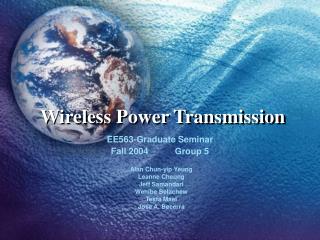
Wireless Power Transmission Alan Chun-yip Yeung Leanne Cheung Jeff Samandari Wehibe Belachew Tesfa Mael Jose A. Becerra EE563-Graduate Seminar Fall 2004 Group 5
Presentation Outline 1. Introduction / Background 2. Theory of Wireless Power Trans. 3. Major Research Projects 4. Comparison of Efficiency … 5. Proposed Project/Experiment 6. Conclusion
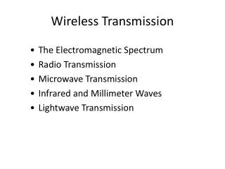
Outline • History/Background • Solar Power Satellite • Microwave Power Transmission • Conclusion Reference: http://www.kentlaw.edu/classes/fbosselm/Spring2004/PowerPoints/Wireless%20Power%20Transmission%20-%20Soubel.ppt
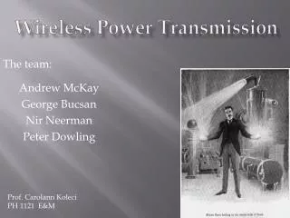
Background, Nikola Tesla • 1856-1943 • Innovations: • Alternating current • Wireless power transmission experiments at Wardenclyffe
Wardenclyffe • 1899 • Able to light lamps over 25 miles away without using wires • High frequency current, of a Tesla coil, could light lamps filled with gas (like neon)
1940’s to Present • World War II developed ability to convert energy to microwaves using a magnetron, no method for converting microwaves back to electricity • 1964 William C. Brown demonstrated a rectenna which could convert microwave power to electricity
Solar Power from Satellites • 1968’s idea for Solar Power Satellites proposed by Peter Glaser • Would use microwaves to transmit power to Earth from Solar Powered Satellites • Idea gained momentum during the Oil Crises of 1970’s, but after prices stabilized idea was dropped • US Department of Energy research program 1978-1981
Problems • Issues identified during the DOE study • Complexity—30 years to complete • Size—6.5 miles long by 3.3 miles wide • Transmitting antenna ½ mile in diameter(1 km) • Cost—$74 billion • Interference
From the Satellite • Solar power from the satellite is sent to Earth using a microwave transmitter • Received at a “rectenna” located on Earth • Recent developments suggest that power could be sent to Earth using a laser
Microwaves • Frequency 2.45 GHz microwave beam • Retro directive beam control capability • Power level is well below international safety standard
Microwave More developed High efficiency up to 85% Beams is far below the lethal levels of concentration even for a prolonged exposure Cause interference with satellite communication industry Laser Recently developed solid state lasers allow efficient transfer of power Range of 10% to 20% efficiency within a few years Conform to limits on eye and skin damage Microwave vs. Laser Transmission
Rectenna “An antenna comprising a mesh of dipoles and diodes for absorbing microwave energy from a transmitter and converting it into electric power.” • Microwaves are received with about 85% efficiency • Around 5km across (3.1 miles) • 95% of the beam will fall on the rectenna
5,000 MW Receiving Station (Rectenna). This station is about a mile and a half long.
Theory of Operation • Electromagnetic Radiation • Antenna basics • Phased-array antenna • Diffraction analogy • Energy distribution • Rectenna • Physical limitations & relationships
Physics of Wireless Power Transmission • Forms of Electromagnetic radiation • Travel at same speed • F = frequency • C = velocity of light • L =wavelength • http://imnh.isu.edu/digitalatlas/clima/atmosph/images/waves.jpg
Dipole Antenna • Transmission of power is simpler than TV & Radio • Transmitter: wire half a wavelength • Pushes electrons back and forth • Receiver: wire half a wavelength http://www.zorg.org/radio/dipole_antenna.shtml
Antenna Radiation Pattern http://www.astromag.co.uk/portable/dipole.gif
Phased-array antenna • The λs for microwaves are small dipoles small • Beam focusing: phased-array antenna • Electronically steered by varying the timing or phase • Waves will merge together http://www.mcs.harris.com/oceannet/features/antenna.html
Phased-Array Antenna http://www.cea.com.au/products/phasedarray/i2_ceafar.html
Diffraction analogy • Light same properties • Laser beam shinning trough a narrow opening & spreads out or diffracts • Bright spot in the center w/fainter spots on the side http://planetquest.jpl.nasa.gov/technology/diffraction.html
Diffraction & Microwaves • Waves reinforce at some points and they cancel out at other points (bright and fainter points) • In microwaves: is a scaled up version of diffraction
Main lobe energy • Circular central max • Main lobe • 84% of energy • Sidelobes surround • No energy minima
Rectenna • Array of dipole antennas known as rectifying antenna or Rectenna • Diameter = Dr
Physical Limitations • The receiving diameter Dr increases with transmitter receiver separation distance S. • Dr increases if transmitter diameter Dt decreases
Calculations/Analysis • Frequency,f(Hz) • Intensity, I(watts per square meter) • Wave-Length, L(meters) • Received Main Beam Lope (“spot”) Diameter, Dr(meters or kilometers) • Transmitting Phased Array Diameter, Dt(meters or kilometers) • Example: how to estimate Intensity, I?
Frequency Formula Dt * Dr • Frequency,f (Hz)= -------------- (2) (L * S) Dt: transmitting phased array diameter Dr: received main beam lobe (“spot”) diameter L: wavelength S: separation
Frequency Analysis Dt * Dr If (Frequency,f(Hz)= ----------- ) 2.44 GHz (2) (L * S) Then at least, 84% of the energy of the beam will be captured Note: • This energy is not linear; 42% of the energy is not equivalent to 1.22 GHz. • Equation (2) represent a best case scenario. • Practical antenna sizes may have to be larger if most of the beam is to be captured. • The rectenna will have to be at least as large as Dt, even if (2) says Dr is smaller.
Frequency Analysis • Such a wide beam can be focused, but only to a minimum size Dr. • For low Earth-orbit power-beaming demonstrations, it is easier to put the smaller antenna in space and the larger antenna on Earth. • Early demonstrations may capture only a small percentage of the total power, in order to keep antenna sizes small. • to light up a 60 watt bulb, thousands of watts may have to be transmitted. • Since costly to launch such a power generating apparatus, the most feasible demonstration project may be Earth-to-space transmission from a large transmitting antenna (such as the Arecibo dish) to a smaller rectenna in space.
Intensity, IFormula • Intensity, I(watts per square meter) P Dt = ½ ( Pi * -----) * ( --------- ) (3) 4 L * S Pi: 3.14… P: total power transmitted Dt: transmitted phased array diameter L: wave length S: transmitter to receiver distance (separation)
Wave-Length, LCalculations • Wave-Length, L(meters) c 300,000,000 meter/sec = ----- = ( -------------------------------- ) = 0.1224 (1) f 2,450,000,000/sec meter c: speed of light f: frequency
Received Main Beam Lope Diameter, Dr Calculations • Received Main Beam Lope (“spot”) Diameter, Dr(meters or kilometers) f * L * S 2.44 * 0.12224m * 35,800,000m = -------------- = -------------------------------------------- Dt 1000m = 10,700 meter = 10.7 kilometers L: wave length S: separation Dt: transmitting phased array diameter
Transmitting Phased Array Diameter, DtCalculations • Transmitting Phased Array Diameter, Dt(meters or kilometers) f * L * S 2.44 * 0.12224m * 35,800,000m = -------------- = ---------------------------------------------- Dr 10,700 meter = 1000m = 1 kilometers L: wave length S: separation Dr: received main beam lope (“spot”) diameter
Example What is the Intensity, I = ? Given: f, Dr, and a typical solar power satellite transmitting 5 billion watts from geostationary orbit 35800 kilometers high. Solution: Use the following (1), (2), & (3) C f = ----- L(1) L Dt * Dr Frequency,f(Hz)= -------------- Dt(2) (L * S) P Dt Intensity, I(watts/m^²) = ½ ( Pi * -----) * ( --------- ) (3) 4 L * S
Example Calculations • Intensity, I(watts per square meter) P Dt = ½ ( Pi * -----) * ( --------- ) (3) 4 L * S 2287485.869w 1000m = ½ ( Pi * ---------------------------) * ( ----------------------------------- ) 4m 0.1224m* 35800,000m = 205 watts/m^² or 20.5 milliwatts/cm^²
Example Analysis • peak beam intensity, Ip = 20.5 milliwatts/cm^² This is abouttwice US industrial standard for human exposure This is converted (by rectenna) to electricity by 90% efficiency • Average intensity, Ia 1/3 * 20.5 milliwatts/cm^²
Rectangular Transmitting antenna array Calculations • Mathematics slightly different, but the same general principles apply. • Central maximum of the beam contain 82% of the transmitted energy. • Rectangular in shape, but will spread out more along TX array’s short direction than its long direction. • Example: Canada’s Radar sat rectangular transmitting antenna: 1.5m × 15m “footprint” on the ground: 7,000m × 50,000m frequency: 5.3 GHz altitude: 800,000m output power: 5000 watts The power is too spread out at the ground to use in a practical demonstration project.
Two more points • Use certain transmitting methods • to reduce the level of the sidelobes • to put some of the sidelobe energy into the main lobe • Price to pay: Larger Rectenna (because main lobe spreads out) • Principal of diffraction also limits the resolution of optical systems: • Lenses • Telescopes
Accomplishments of Solar Power Satellites • 1980, 30 kW of microwave power was transmitted to a receiving antenna over one mile • 1993, Japan successfully transmitted a 800W microwave beam from a rocket to a free-flying satellite in space. • 1998, Microwave to DC conversion efficiency of 82% or higher by the rectenna.
NASA’s 1995-1997 Fresh Look Study • MEO (Mid-Earth Orbit) Sun Tower: - 6 SPS yields near 24-hr power to sites - ± 30 degrees Latitude Coverage - Power services of 200-400 MW