Mars Rover Project
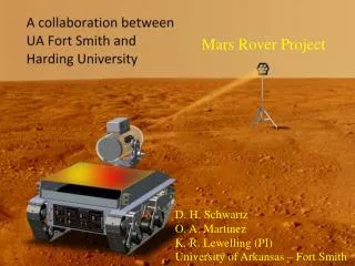
Mars Rover Project. D. H. Schwartz O. A. Martinez K. R. Lewelling (PI) University of Arkansas – Fort Smith. Rover chassis built by Harding University. +/- 15 V Power Supplies. Motor Drive Circuit. Rover Code. /* Code to DEMO ROVER SIGNAL AND PORT CONNECTIONS:

Mars Rover Project
E N D
Presentation Transcript
Mars Rover Project D. H. Schwartz O. A. Martinez K. R. Lewelling (PI) University of Arkansas – Fort Smith
Rover Code /*Code to DEMO ROVER SIGNAL AND PORT CONNECTIONS: PT7 PT6 PT5 PT4 PT3 PT2 PT1 PT0 PB7 PB6 PB5 PB4 PB3 PB2 PB1 PB0 | | | | | | | | GND 5V CS CSDIS ENB INB INA ENA */ #include <hidef.h> /* common defines and macros */ #include <mc68hc912d60.h> /* derivative information */ #include <stdlib.h> int x; int y; int z; void main(void); void MSDelay(unsigned intitime); void Forward(unsigned int DTY); void Reverse(unsigned int DTY); void TurnRight(void); void TurnLeft(void); void Brake(unsigned int DTY1, unsigned int DTY3); void Stop(void);
void main(void) { COPCTL = 0x08; PWPOL = 0xEF; /* Pulse clock select and polarity, REG 0041*/ PWPER1 = 0x65; /* Sets period for PWM bit 1, REG 004D*/ PWPER3=0x65; /* Sets period for PWM bit 3*/ PWSCAL0 = 0x06; /* Used for PWM channels 0 and 1, allows selection of clock S0, REG 0045*/ PWSCAL1 = 0x06 ; PCKA0=0; //clock A for channels 0 and 1 PCKA1 =1 ; PCKA2 =1; PCKB0 =0; // clock B for channel 2 and 3 PCKB1 =1; PCKB2 =1; PWEN = 0x0F; /* Enables PWM bit 1 and bit 3 REG 0042*/ DDRT = 0xFF; /*Enables PORT T*/ DDRB =0xFF; /*Enables PORT B*/ PORTT=0x7F; /*Rover is Brake*/ PORTB=0x7F; /*Rover is Brake*/ Stop(); Forward(30); Brake(PWDTY1,PWDTY3); Stop(); Reverse(30); Brake(PWDTY1,PWDTY3); Stop(); TurnRight(); Brake(PWDTY1,PWDTY3); Stop(); TurnLeft(); Brake(PWDTY1,PWDTY3); Stop();
Rover Lower and Upper Arm Lower Arm Upper Arm
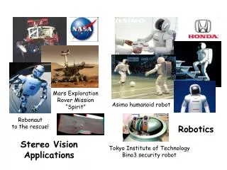
Next Steps • Mount arm on rover • Develop gripping mechanism • Develop drilling attachment • Add machine vision (MV) • Program autonomous guidance using MV • Add IR spectrometer
Acknowledgements • NASA • Arkansas Space Grant Consortium • Ken Gibson – ABB Baldor • Kevin Lewelling – University of Arkansas Ft. Smith • Osman Martinez –University of Arkansas Ft. Smith • Edmond Wilson – Harding University • University of Arkansas Fort Smith • Harding University