Mini-Review of Motion Control Architecture for NGAO: Overview and Key Findings
320 likes | 435 Vues
This mini-review outlines the motion control architecture of the Next Generation Adaptive Optics (NGAO) system, focusing on the various types and locations of motion control devices. It details the review agenda, including welcome comments, discussions on requirements compliance, and assessing the proposed architecture. Key areas of focus include the types of motion controls, their design status, and potential concerns regarding maturity and feasibility. The review emphasizes the importance of achieving precise motion control to enhance NGAO performance.

Mini-Review of Motion Control Architecture for NGAO: Overview and Key Findings
E N D
Presentation Transcript
Motion Control Architecture Mini-Review Contributors: Ed Wetherell, Kevin Tsubota, Jason Chin 11 Mar 2010
Schedule The agenda for the review is as follows (times are HST): • 8:00 AM: Welcome and introductions • 8:10 AM: Presentation • 9:15 AM: Break • 9:30 AM: Review Comments/ Open discussion • 10:30 AM: Review committee closed session • 11:00 AM: Review committee feedback to team
Agenda • Review Committee Charter • Scope of the Review • Requirements Compliance • Motion Control • Types • Locations • Architectures • Design Status • Review Committee Comments • Summary of Concerns • Plans for PDR
Review Committee Charter • Reviewers: Don Gavel (UCO, chair) Alex Delacroix (CalTech) Tomas Krasuski (WMKO) • Are the requirements understood? • Does the proposed architecture satisfy the requirements? • Is the architecture • Complete? • Technically feasible? • Cost effective? • Is the architecture sufficiently mature that it can be developed to the PDR level by the 2nd Qtr of 2010?
Scope of the Review • Motion control electronics architecture • Control of actuated devices used throughout the various NGAO subsystems • Not in the scope of this review: • Overall architecture of the NGAO control system or the top-level design of the NGAO control system • Motion control required for real-time wavefront correction (DMs, T/T) under control of the RTC • Software controls • Effort Estimates • Budget • Schedule
Requirements Compliance • Locating all of the relevant requirements has proven challenging • Every subsystem was reviewed for requirements relating to motion control • PD Requirements Review (Phase II) week of 1March, continued into week of 7March • Impact on motion controls has yet to be assessed • More effort required to • Verify all requirements have been identified • Determine compliance • Address deficiencies in requirements and compliance • No areas of non-compliance have been identified
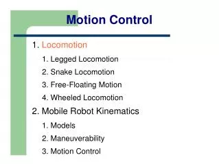
Motion Control Types (1) • Shutters • Simple in/out devices with very loose positional requirements • Actuators other than motors (e.g., solenoid, pneumatic, etc.) may be considered • Switches or hard stops may be used to define the positions, encoders not required • Knowledge of actual position when moving, although desirable, is not required • Low precision, non-tracking • A dichroic or fold, for example, that is either in the beam or out of the beam • Moved during configuration, not during an observation • Position with encoder • Medium precision, non-tracking • Higher precision, still primarily single axis devices • Moved during configuration, not during an observation • Likely combine this category with Type 1 devices • High precision, non-tracking • aligning a lenslet or focusing a unit • moved during configuration or acquisition, not during an observation
Motion Control Types (2) • Tracking • position calculated from and synchronized to external information (telescope az/el, etc) • servo loops closed during an observation, command rates of 25mS to 100s of seconds • generally more stringent requirements on servo loop performance • want smooth motion, small following error, minimal overshoot • various levels of precision required • ADC, rotators • Extremely high precision tracking and non-tracking • coordinated motion with other DOF(s) • may be constantly moving during an observation, update rates of 1Hz or faster • generally requires a high precision actuator, not a servo motor • examples include steering mirrors and tip/tilt stages • Pickoff arms - coordinated high precision non-tracking • most demanding DOF • position calculated from and synchronized to external information (telescope az/el, etc) • coordinated motion with other DOF(s) • spatial position constraints to avoid collision • mechanical design may require the device to servo in position
Location Overview Current NGAO System Total: 54 AO + 29 Laser = 83 DOF Original Estimate: 150+ DOF Existing K2AO system: 29 AO + 22 Laser = 51 DOF
Motion Control Architecture (1) • Centralized • All components are rack-mounted in a single location • Individual cables flow from the rack to each DOF • Primary approach taken throughout the observatory • Pros • Familiarity • Straight forward heat / power management • Single starting point for troubleshooting • Potential for reuse of SW and/or HW • Cons • Cabling – lots of it to a single location • Longer cables may exclude use of low cost PWM amplifiers • Scalability due to space constraints • Proposed use • AO Electronics Vault • Most AO devices • Telescope Secondary or Laser Service Enclosure • Laser Beam Generation System devices • Laser Switchyard devices if equipment in LSE
Motion Control Architecture (2) • Distributed • Equipment located in close proximity to actuator • Several options with varying amounts of distributed equipment • Distributed amplifier, central controller • Distributed controller and amplifier • Smart motor: controller and amplifier integrated into motor • Pros • Significant reduction in cabling effort • Very scalable • Possible improvement in servo bandwidth • Short cables allow use of lower cost PWM drives for some axes • Allows partial system reset which may reduce the recovery time • all stages may not require homing • Cons • Distributed thermal loads • Troubleshooting requires knowledge of physical layout with multiple device locations • Integration with E-stop system • Propose use of smart motors for low/moderate precision non-tracking devices
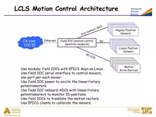
Design Status (1) • Controllers • Use of programmable, multi-axis controllers with Ethernet • Delta-Tau PowerPMAC a possibility • Use of coordinate systems for multi-axis stages • Prefer distributed control system to communicate via engineering units (mm, field position), not encoder counts • Translation at the controller level • Actuators • must operate in specified environment: -15°C in cold box, -10°C on secondary • DC motors (brush or brushless) • Drive or load position encoding, precision dependant • Precision actuators (piezo t/t stages, linear piezo, voice coil, etc) • Smart motors • Normally closed (open when triggered) end of travel switches • Crates / processors • Separate embedded processors (VxWorks) likely not required • Higher level server to handle communications and monitoring functions
Design Status (2) • Observatory E-stop interface • Part of the motion control requirements • Will likely remove power to all motion amplifiers • Preferably preserve encoder/limit switch power to easy recovery • Cables will need to remain flexible at operating temp • Combine multiple axes on single cable where possible • -15°C in cold box, -10°C on secondary • Attention needed on pickoff arms and devices mounted to an in/out or focus stage to provide adequate range of travel • Motors supplied with an integral cable could be a challenge • Instrument mechanisms • Not part of NGAO motion control design • Imager+IFS (DAVINCI) has its own motion controls • Interferometer DSM supported by IF ancillary electronics rack and IF control system • Interferometer will have devices on AO bench • Devices will be controlled by NGAO to eliminate any impact on non-IF AO observing • Details not known
Proposed Layout of AO Controls on Left Nasmyth • Multi-axis servo controllers located in e-vault • Smart motors used for intermittent, low or moderate precision devices • 6 of these motors inside the cold box, 3 outside • Continuous power dissipation of ~0.9 W each • Stages must accept NEMA frame motor • Requires power supply and terminal server port • estimate ~$400/axis savings (procurements) over centralized approach • 32 servo devices on cold bench • anticipate ~15 W (total, 0.5 per device) of power for encoders alone • some DOF in the Cal/Sim unit may have dedicated controllers • 13 devices in AO Room • 7 servo motors, 6 piezo (or equivalent) • Cabling • Anticipate around 16 cables between cold box and e-vault • Assumes 2 DOF per servo motor cable • Cold box will have bulkhead connectors; environmental seal but not hermetic • Interface with facility Emergency Stop • Prevent motion to protect personnel and equipment • Keep encoders/limits powered if possible to speed recovery • Volume ~ 22U (half 7 foot rack), similar to existing AO system
Proposed Layout of Laser devices w/ controllers in LSE • Motion controllers for laser switchyard and beam generation system located in LSE • Pro: • Limited requirement on Elevation cable wrap • Space, power and glycol are available in LSE • Con: cables between secondary and LSE • Cabling • Anticipate 18 cables between LSE and secondary • 12 of the 18 for the linear piezo devices, may be able to combine into fewer cables • Only infrastructure cables (power, Ethernet, time sync, e-stop) between LSE and e-vault • Volume: 15U of 19” rack (~0.12 m^3)
Alternate Layout of Laser devices w/ controllers on Secondary
Alternate Layout of Laser Devices w/ controllers on Secondary • Controllers for BGS devices located on secondary, Switchyard controlled from e-vault • Pro: Minimal cabling to secondary • Con: • Space and mass on secondary • Will require (custom?) cooled enclosure for electronics • LSE cables in elevation wrap • Cabling • Requires infrastructure cables (power, Ethernet, time sync, e-stop) between secondary and e-vault • 10 motion cables between LSE and e-vault (el wrap) • Volume: 10U of 19” rack (0.08 m^3)
Alternate Layout of Laser devices w/ all controllers in E-vault • Controllers for all laser devices located in E-vault (not illustrated) • Pro: • Heat/power management • Con: • Some equipment still likely in LSE or secondary • Would require cooled enclosure • 40m cables from secondary to e-vault, through elevation wrap • Devices must meet spec • Voltage drop across cable must be managed • Differential drivers required for encoders • Actuators with single-ended encoders would require design of custom driver board • LSE cables in elevation wrap • Cabling • 18 cables between secondary and e-vault • may be able to reduce this to 12 • 10 cables between LSE and e-vault • Volume: 15U of 19” rack (0.12 m^3) in e-vault
Review Committee Comments(1) • Mahalo to everyone for your detailed review of this material • Revision to documents forthcoming
Review Committee Comments(2) • Need definition of terms • Reviewers noted inconsistency of naming • Project needs to publish preferred names and definitions • Need agreement on required controls (tracking) and precision of devices • Perhaps some differing ideas about definition of tracking • Servo loops closed during observation • Recycling of existing equipment (OBS) • Not likely despite apparent compatibility • Much is obsolete or would require upgrade • Concern about smart motors inside cold enclosure • Not a significant heat source, compared to traditional motors • Some in-house testing is required to verify manufacturer claims • Changing the design to conventional servo motors straight forward
Review Committee Comments(3) • Comment regarding controls split between AO and IF in current system • NGAO will control all devices on AO bench • NGAO will control all hatches • Eliminate problems in existing distribution of control • NGAO will need the output hatches closed during observing (and presumably daytime prep/stabilization) • NGAO is required for IF observing, the converse is not true. IF should not be required for NGAO to work • Is there any allocation for expansion? • Not in the strict sense of x% free channels • Need guidance from the project • Adding smart motors to the ring is easy • Probably a limit based on communication bus speed • Depending on choice of controller, expansion would only be limited by available rack space
Review Committee Comments(4) • Type and amount of diagnostics was questioned • This needs work. • At present, no additional hardware is anticipated • Heat analysis of Cold Enclosure • Estimate of steady state load provided • ~20W of encoder • Active limit switches have negligible contribution • Active state much harder to predict • Need payload information from subsystems designers to estimate required motor power • Need duty cycle information for devices with intermittent motion • Work with Mechanical engineers to estimate thermal constants of enclosure • Need analysis of how thermal gradients , bench ‘seeing’, local hot spots, etc. impact performance
Review Committee Comments(4) • Reviewer suggests a survey of existing motion systems for ‘likes’ and ‘dislikes’ • Worthwhile • Some of this is already included given the experience of the team on both AO an IF • Reviewer comment on missing reference on pg13 of KAON 715 • Typo, should be KAON 643 section 7.6 (not 6.7), will be corrected • Reviewer responded to concerns about probe arm limit switches • Updated design that uses load cells to determine direction of travel • This helps recover from a limit condition • Concern about interface to motion control system • Still a concern about homing these stages • Reviewer concern about flow-down requirements listed in KAON 715 • These are flow-down, not functional requirements • Not aware of a decision to manage this type of requirement in Contour
Reviewer Feedback • Any questions? • Detailed responses to individual comments are (or will be) posted on the TWiki
Summary of Concerns (1) • Better collaboration between subsystem design teams • Need agreement on required controls and precision of devices • Need completion of Master Device List with all relevant information • Need better understanding of pickoff arm controls (homing)
Summary of Concerns (2) • Nearly every subsystem requires motion control • Insufficient detail on some subsystem designs • Need to understand goals for DD and I&T • Which team is responsible for what • How much duplicate equipment is required in California • What level of performance validation is performed by subsystem designers • Understand cabling requirements • Clean enclosure • work out baseline for connectors/cables • Telescope cable wraps
Plans for PDR • Work with Systems Engineering to get a complete approved set of requirements • Work with subsystem designers to complete the Motion Control design • Decide on location of laser control electronics • Provide estimates for power/volume/mass • Maintain KAON 682 (Master Device List) • Complete KAON 715 (Preliminary Motion Control Design) • Identify risks and mitigation plans • Budget and Schedule
Review Comittee Session • Given the short time to the PDR, we request an informal report via email, rather than a formal write-up • this will decrease the turn around time and limit additional effort required by the reviewers • If the reviewers prefer a formal write-up, please provide this within a week