MOTION CONTROL
MOTION CONTROL. MPM UP3000 UltraFlex SERIES PRINTERS. Steven Ng June 2000. At the end of this presentation, you will understand the theory behind motion control on the MPM UP3000 UltraFlex stencil printer. Let’s get started !. Move X Axis + direction !!!.

MOTION CONTROL
E N D
Presentation Transcript
MOTION CONTROL MPM UP3000 UltraFlex SERIES PRINTERS Steven Ng June 2000
At the end of this presentation, you will understand the theory behind motion control on the MPM UP3000 UltraFlex stencil printer Let’s get started !
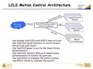
Move X Axis + direction !!! UP3000 UF Functional Block diagram (Motion) PC/ Software Primary Voltage TV2 120VAC GS1 24VDC PCDIO Card Limit Sensor M Motion Control Card TV1 52VAC I/O Mother Board Motion Mother Board Bridge Rectifier 70VDC MUX Card Step Driver Software tells the MCC What to do !
UP3000 UF Functional Block diagram (Motion) PC/ Software Primary Voltage TV2 120VAC GS1 24VDC PCDIO Card Limit Sensor M Motion Control Card TV1 52VAC I/O Mother Board Motion Mother Board Bridge Rectifier 70VDC MUX Card Step Driver MOTION CONTROL CARDS: ALL MOTION SIGNALS START AND END HERE !!!!!
Move X Axis + direction !!! UP3000 UF Functional Block diagram (Motion) PC/ Software Primary Voltage TV2 120VAC GS1 24VDC PCDIO Card Limit Sensor OK, I will M Motion Control Card TV1 52VAC I/O Mother Board Motion Mother Board Bridge Rectifier 70VDC MUX Card Step Driver The MCC Receives the signal and does it’s thing
UP3000 UF Functional Block diagram (Motion) PC/ Software Primary Voltage TV2 120VAC GS1 24VDC PCDIO Card What’s behind Door # 10 ?? Limit Sensor M Motion Control Card TV1 52VAC I/O Mother Board Motion Mother Board Bridge Rectifier 70VDC MUX Card Step Driver It sends a signal through the MMB to the MUX to Open a channel (or door )
UP3000 UF Functional Block diagram (Motion) PC/ Software Primary Voltage TV2 120VAC GS1 24VDC PCDIO Card Limit Sensor M Motion Control Card TV1 52VAC I/O Mother Board Motion Mother Board Bridge Rectifier 70VDC MUX Card Step Driver MOTION MOTHER BOARD: PASSIVE BOARD THAT HOLDS THE MUX BOARDS
UP3000 UF Functional Block diagram (Motion) PC/ Software Primary Voltage TV2 120VAC GS1 24VDC PCDIO Card Limit Sensor M Motion Control Card TV1 52VAC I/O Mother Board Motion Mother Board Bridge Rectifier 70VDC MUX Card Step Driver MUX BOARD: 5 CHANNEL MULTIPLEXER CARD. Capable of 1 axis of motion at a time.......
UP3000 UF Functional Block diagram (Motion) PC/ Software Primary Voltage TV2 120VAC GS1 24VDC PCDIO Card Limit Sensor M Motion Control Card TV1 52VAC I/O Mother Board Motion Mother Board Bridge Rectifier 70VDC MUX Card Step Driver THERE ARE 8MUX CARDS ON THE MOTION MOTHER BOARD
MUX 1 THROUGH 4 ARE CONTROLLED BY MCC # 1 MCC # 1 MUX Card # 1 MUX Card # 2 MUX Card # 3 MUX Card # 4
MUX 5 THROUGH 8 ARE CONTROLLED BY MCC # 2 MCC # 2 MUX Card # 5 MUX Card # 6 MUX Card # 7 MUX Card # 8
Each MUX card has it’s own group of DRIVERS MUX Card # 1 Channel # 0 Channel # 4 Channel # 1 Channel # 3 Channel # 2 Driver Card E 10 Driver Card E11 Driver Card E12 Driver Card E13 Driver Card E14
UP3000 UF MUX ADDRESS MUX Card # 1 MUX Card # 2 MUX Card # 3 MUX Card # 4 Channel 0 = X Axis Channel 0 = Y Axis Channel 0 = * Theta Axis Channel 0 = * Z Axis Channel 1 = Wiper L& R Channel 1 = SQ Down stop Channel 1 = Paste Dispenser Channel 1 = C Trk Transport Channel 2 = C Trk Width Channel 2 = I/O Trk Width Channel 2 = SQ Stroke Channel 2 = R I/O Trk Width Channel 3 = Cart Index Channel 3 = Spare Channel 3 = Spare Channel 3 = Rack Sten L & R Channel 4 = Z Track Channel 4 = Spare Channel 4 = Spare Channel 4 = Rack Up/Down MUX Card # 5 MUX Card # 6 MUX Card # 7 MUX Card # 8 Channel 0 = Vision X Channel 0 = Vision Y L & R Channel 0 = L I/O Transport Channel 0 = R I/O Transport Channel 1 = Stencil Retr L & R Channel 1 = Tactile Z Channel 1 = Spare Channel 1 = Spare Channel 2 = Spare Channel 2 = Spare Channel 2 = Spare Channel 2 = Spare Channel 3 = Spare Channel 3 = Spare Channel 3 = Spare Channel 3 = Spare Channel 4 = Spare Channel 4 = Spare Channel 4 = Spare Channel 4 = Spare Note : * Left Driver Pod
UP3000 UF Motor Reference Guide Axis Description Assembly M 10 “X” Axis 1000285 M 11A Wiper Left CA-270-6 M 11B Wiper Right CA-270-7 M 12 Centre Track Width 1000289 M 13 Indexer 1000307 M 14A Z Track, Front Left 1006894 M 14B Z Track, Front Right 1006894 M 14C Z Track, Rear Left 1006894 M 14D Z Track, Rear Right 1006894 M 20 “Y” Axis 1000286 M 21 SQ Down Stop 1000291 M 22 Left Width 1000298 M 30 Theta Servo Motor 1006900 M 31 Paste Dispenser 1000294 M 32 Squeegee Stroke 1000292 M 40 Z Servo Motor 1005789
UP3000 UF Motor Reference Guide Axis Description Assembly M 41A Centre Transport 1007234 M 41B Centre Transport 1006969 M 42 Right I/O TRK Width 1000300 M 43A Stencil Drive Left 1000305 M 43B Stencil Drive Right 1000304 M 44 Stencil Rack 1000306 M 50 Vision “X” 1000295 M 51A Retractor Left 1000303 M 51B Retractor Right 1000302 M 60A VY Left 1000296 VY Right 1000297 M 60B M 61 Tactile 1000293 M 70A Left Transport 1000299 M 70B Left Transport 1000311 M 80A Right Transport 1000301 M 80B Right Transport 1000312
UP3000 UF Driver DIP Switch & Jumper Settings Driver Driver Name DIP Switch J5 J6 Pod 1 2 3 4 5 6 7 8 11,13 1,2 3,4 5,6 7,8 E10 X-AXIS C O C O C O C O IN IN IN OUT IN E11A WIPER LEFT O C C O C C O O IN IN IN OUT OUT E11B WIPER RIGHT O C C O C C O O IN IN IN OUT OUT E12 CENTRE TRACK WIDTH C O C O C O C O IN IN IN OUT IN E13 CARTRIDGE INDEX C O C O C O C C IN IN IN OUT OUT E14 Z TRACK C O C O C O C O IN IN IN OUT OUT E20 Y-AXIS C O C O C O C O IN IN IN OUT IN E21 SQUEEGEE DOWN STOP C O C O C O C C IN IN IN OUT OUT E22 LEFT I/O TRACK WIDTH C O C O C O C C IN IN IN OUT OUT E31 PASTE DISPENSER C O C O C O C C IN IN IN OUT OUT E32 SQUEEGEE STROKE C O C O C C C C IN IN IN OUT OUT E41 CENTRE TRK TRANSPORT C O C O C C O C IN IN IN OUT OUT E42 RIGHT I/O TRKWIDTH C O C O C O C C IN IN IN OUT OUT
UP3000 UF Driver DIP Switch & Jumper Settings Driver Driver Name DIP Switch J5 J6 Pod 1 2 3 4 5 6 7 8 11,13 1,2 3,4 5,6 7,8 E43A RACK STENCIL LEFT C O C O C O C C IN IN IN OUT OUT E43B RACK STENCIL RIGHT C O C O C O C C IN IN IN OUT OUT E44 RACK UP/DOWN C O C O C O C C IN IN IN OUT OUT E50 VISION X O C C O C O C O IN IN IN OUT IN E51A STENCIL RETR LEFT C C O O C C O C IN IN IN OUT OUT E51B STENCIL RETR RIGHT C C O O C C O C IN IN IN OUT OUT E60A VISION Y LEFT O C C O C O C C IN IN IN OUT IN E60B VISION Y RIGHT O C C O C O C C IN IN IN OUT IN E61 TACTILE Z (P4720) C O C O C O C C IN IN IN OUT OUT E70 LEFT I/O TRANSPORT C O C O C C O C IN IN IN OUT OUT E80 RIGHT I/O TRANSPORT C O C O C C O C IN IN IN OUT OUT
E10 Driver #s indicate MUX location !!! MUX 1 CHAN 0 IN-LINE CONNECTORS MOTOR # 10
E10 Driver #s indicate MUX location !!! MUX 1 CHAN 0 MUX # 1 CHANNEL # 0 MOTOR # 10
E10 Driver #s indicate MUX location !!! P/J 110 MUX 1 CHAN 0 IN-LINE CONNECTORS CONNECTOR #110 IS THE FIRST CONNECTOR IN LINE MOTOR # 10
E10 Driver #s indicate MUX location !!! P/J 110 MUX 1 CHAN 0 IN-LINE CONNECTORS MOTOR # 10 E10 IS DRIVER # 10
E10 Driver #s indicate MUX location !!! P/J 110 P/J 210 P/J 310 MUX 1 CHAN 0 IN-LINE CONNECTORS P/J 410 CONNECTOR #210 IS THE SECOND CONNECTOR IN LINE MOTOR # 10
40 POSSIBLE AXES OF MOTION 8 AT ONE TIME
The signals for motion originate in the Motion Control Cards. STEP DIRECTION MCC # 1 COMMON STEP DIRECTION MCC # 2 COMMON
The signals for motion originate in the Motion Control Cards. STEP MCC TheSTEP signal triggers a green LED on the MCC in the computer. It can not be measured with a standard voltmeter
The signals for motion originate in the Motion Control Cards. + 5VDC 0VDC DIRECTION MCC The DIRECTION signal does NOT trigger an LED. You can *measure the signal with a standard voltmeter. * Note: Hold the positive meter lead to the DIR wire (Pin 7) and common to the COM wire (Pin 1) at driver J1 connector, roll the trackball.
The signals for motion originate in the Motion Control Cards. + 5VDC 0VDC DIRECTION MCC The signal is switched from +5VDC to 0VDC by changing the direction of the TRACKBALL.
The signals for motion originate in the Motion Control Cards. + 5VDC 0VDC DIRECTION MCC This signal determines which direction the AXIS will move..... POSITIVE for +5VDC NEGATIVE FOR 0VDC
The signals for motion originate in the Motion Control Cards. 4 Controls motors 10-14 20-24 30-34 40-44 MCC # 1 Controls motors 50-54 60-64 70-74 80-84 MCC # 2 Each Card has 4 Channels for Signal OUTPUTS....
The signals for motion originate in the Motion Control Cards. 4 Controls motors 10-14 20-24 30-34 40-44 MCC # 1 Controls motors 50-54 60-64 70-74 80-84 MCC # 2 AND ...... 4 Channels for Signal INPUTS !
UP3000 UF Functional Block diagram (Motion) PC/ Software Primary Voltage TV2 120VAC GS1 24VDC PCDIO Card MUX # 1 Channel # 0 Limit Sensor M Motion Control Card TV1 52VAC I/O Mother Board Motion Mother Board Can I help you ? Bridge Rectifier 70VDC MUX Card Step Driver In this case it is Driver E10 or Mux 1 channel 0
UP3000 Hi-E Functional Block diagram (Motion) PC/ Software Primary Voltage TV2 120VAC GS1 24VDC PCDIO Card OOHH, OK, Positive DIR. Here’s 5VDC Limit Sensor M Motion Control Card TV1 52VAC I/O Mother Board Motion Mother Board This Tickles ! Bridge Rectifier 70VDC MUX Card Step Driver At the same time, a 5VDC signal is sent on another Cable to the MUX for the driver signal.
UP3000 UF Functional Block diagram (Motion) PC/ Software Primary Voltage TV2 120VAC GS1 24VDC PCDIO Card Step, Step, Step Step, etc... Limit Sensor M Motion Control Card TV1 52VAC I/O Mother Board Motion Mother Board Oh Boy ! Step signal…. Bridge Rectifier 70VDC MUX Card Step Driver And a STEP signal is also sent to the MUX for the driver signal.
UP3000 UF Functional Block diagram (Motion) PC/ Software Primary Voltage TV2 120VAC GS1 24VDC PCDIO Card Step, Step, Step Step, etc... Limit Sensor M Motion Control Card TV1 52VAC I/O Mother Board Motion Mother Board Here Mr. Drive Now, DRIVE ! Bridge Rectifier 70VDC MUX Card Step Driver The Mux sends the STEP and DIRECTION Signals to the DRIVER...
UP3000 UF Functional Block diagram (Motion) Our drivers operate on 65-70 VDC The Model 6410 Drivers will not operate if the voltage exceeds 75VDC
Primary Voltage Stepper Power QF 1 Main Disconnect/Breaker K1 Main Power Relay How Does This Happen ? TV1 52VAC
UP3000 UF Functional Block diagram (Motion) WAKE UP !!!!! 240V TV1 This is a Transformer that takes the Primary Voltage( 240V) and drops it to a Secondary Voltages. In this case it is dropped to: 52 VAC 52VAC
Primary Voltage UP3000 UF Functional Block diagram (Motion) TV1 Transformer is a MULTITAP Transformer By changing the location of the incoming power on TV1, you can raise or lower the SECONDARY Power. TV1 ? 52 VAC ??? VAC
Primary Voltage IN at TV1 AC 208-240 240 VAC DC AC
0 104 110 120 0 208 220 240 Match Taps with Primary Voltage In TV 1 52VAC 52VAC Neutral 57VAC Simplified diagram of a multi-tap Transformer
Secondary Voltage at TV1 52 VAC DC AC
Bridge Rectifier 70VDC UP3000 UF Functional Block diagram (Motion) TV1 52VAC
Bridge Rectifier 70VDC FROM AC TO DC VOLTS ? UP3000 UF Functional Block diagram (Motion) TV1 52VAC 52VAC is converted to 70VDC
Bridge Rectifier UP3000 UF Functional Block diagram (Motion) Three Bridge rectifiers Located in Driver pod left side A Bridge Rectifier is a device comprised of 4 diodes that Changes AC volts to DC volts Our drivers operate on 65-70 VDC
UP3000 UF Functional Block diagram (Motion) Rectifier Each Bridge Rectifier has it’s own Fuses in the AC Pod
UP3000 UF Functional Block diagram (Motion) Capacitor: Our Machines use Capacitors in order to filter the DC Voltage to the Step Drivers. Primary Voltage TV1 52VAC Bridge Rectifier 70VDC • Capacitor
UP3000 UF Functional Block diagram (Motion) There are total of 5 Capacitors In the Driver Pod Primary Voltage TV1 52VAC Bridge Rectifier 70VDC • Capacitor
UP3000 UF Functional Block diagram (Motion) C1 C2 C3 C4 C5 Each cap or each set of caps feed it’s OWN group of drivers.
UP3000 UF Functional Block diagram (Motion) K14 C1 VC1 K12 C2 VC2 Rectifier C3 K13 C4 VC3 Capacitor C5 The Bridge Rectifiers each feed a Cap or set of Caps Individually.