Download
1 / 38
380 likes | 497 Vues
Discover the functionality and architecture of Cisco CallManager (CCM), a key component of Cisco’s AVVID solution for IP telephony. This software-based module enables call routing, signaling, and device management for up to 2,500 devices in a cluster, expanding telephony capabilities. Learn about its interactions with IP phones, media processing devices, and how it manages configuration through TFTP and DHCP. The CCM supports advanced features like music on hold, call dispatching, and database handling to ensure seamless communication and administration across networks. Ideal for IT professionals in telecommunications.

E N D
BAI613Packet Telephony Module 6 Enterprise IP telephony
SW-based, call processing piece of Cisco’s AVVID solution Architecture for Voice, Video, and Integrated Data CCM is the call-routing and signaling component Overview
Cisco has collaborated with both IBM and HP-Compaq to manufacture the Cisco Media Convergence Servers (MCS) . Now the CCM software can be sold separately without buying the hardware from Cisco Most are rack-mountable except for the model we use (MCS 7825) There are currently 4 other models Windows 2000 800 MHz Intel III processor 512 MB RAM 20 GB Fast ATA Hard Drive Maximum of 500 IP phones standalone Server Maximum 2500 IP Phones in a cluster Hardware Requirements
Call processing Signaling Device (phone) management Dial Plans Other features Phone key mappings, etc. IP phones communicate with CCM via Cisco proprietary “Skinny” protocol IP phones inter-communicate using RTP CCM Functions
CCM Provides signaling and media control signaling for up to 2500 devices Cisco IP Voice Media Streaming Applications Provides H.323 media termination. Music on Hold, and G.711 media mixing capabilities Cisco MOH Audio Translator Converts G.711 music source files to G.729a music source files for providing to G.729a capable devices W2K Services on Cisco AVVID Telephony Servers
Cisco RIS Data Collector Collects serviceability information from all cluster members for improved administrability. Cisco Telephony Call Dispatcher Allows users such as switchboard attendants to receive and quickly transfer calls to other users; provides automated routing capabilities Cisco TFTP Provides preregistration information to devices, including a list of CCM servers with which the devices are permitted to register, firmware loads, and device configuration files W2K Services on Cisco AVVID Telephony Servers (cont.)
Database Notification Change notification server and watchdog process that ensures that all IP telephony applications running on a server are working properly Publisher Database Serves as the primary read-write data repository for all IP telephony applications in the cluster. This database replicates updates to all Subscriber databases in the cluster Subscriber Database Serves as backup read-only database for IP telephony applications running on the server, should the applications lose connectivity to the Publisher database W2K Services on Cisco AVVID Telephony Servers
Client Devices Supported by CCM Station Devices Generally IP telephony handsets May also be H.323 clients such as NetMeeting May also be IP softphones Gateway Devices Provide access from one telephone system to another CCM to another CCM CCM to a PBX CCM to the PSTN Typically use H.323 or MGCP Client Devices Supported by CCM
Media Processing Devices Transcoding Resources Perform codec conversions between devices that do not encode voice conversations using a common encoding scheme Unicast Conferencing Devices Permit Ad Hoc and Meet-Me conferencing Media Termination Point (MTP) Resources Allow users to invoke features such as Hold or Transfer even though one of the endpoints does not support them Music on Hold (MOH) Resources Provide users access to music sources when they are placed on hold Client Devices Supported by CCM (cont.)
IP Phones need access to a TFTP Server that contains device loads and configuration files The DHCP Server will automatically direct the devices to the TFTP Server (Option 150 in the DHCP Scope) If a device has been manually added into the Cisco Call Manager database, the device accesses a configuration file corresponding to its device name. If auto-registration is enabled in Cisco Call Manager, the phones access a default configuration file from the TFTP server. Understanding how devices use TFTP and DHCP Server
After obtaining the configuration file from the TFTP server, a device attempts to make a TCP connection to the highest priority Cisco Call Manager in the list specified in the configuration file. If the device was manually added to the database, Cisco Call Manager identifies the device. If auto-registration is enabled in Cisco Call Manager, phones that were not manually added to the database attempt to auto-register in the Cisco Call Manager database. Cisco Call Manager informs devices using .cnf format configuration files of their load ID. Devices using .xml format configuration files receive the load ID in the configuration file. If the device load ID differs from the load ID that is currently executing on the device, the device requests the load associated with the new load ID from the TFTP server and resets itself. Once a telephone is ready to make a call, it will request an available ringer list from the TFTP server. If the telephone user changes the ring type, the TFTP server sends the new ring type. Connecting to the Call Manager Reference: Cisco Call Manager System Guide Version 3.2 from www.cisco.com
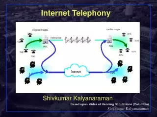
Step 1: Call Signaling Using the Skinny protocol, the IP phone sends a request to the CCM to originate a call. Request contains address of destination. CCM locates called party, sends a new call event to to the called device, and waits for called party to respond with answering event AVVID Call Establishment
Step 2: Media Control As called party answers, CCM determines details of media session to be established. CCM must ensure that both devices can communicate using a common encoding scheme and CCM must provide IP address and port on which called device has chosen to receive data AVVID Call Establishment (cont.)
Step 3: Media Exchange Once media session is successfully negotiated, devices communicate through IP network infrastructure using RTP/UDP/IP protocols. AVVID Call Establishment (cont.)
DHCP Services must be running on the PC Start – Programs – Administrative Tools – Services Double-click DHCP Server Change Startup type: to Automatic and click Apply Click Start and wait until the service has started Click okay to close window Under Services window, DHCP Server should now indicate Started under Status and Automatic under Startup Type Close this window Initial CCM Setup
Start – Programs – Administrative Tools – DHCP Under the Action menu, select Add Server Click Browse and your server will show up by name Hi-light your server and click OK Your server will now show up in the DHCP window An hour-glass will be apparent to the left of the server IP address. Once this disappears, it will be replace by a green arrow indicating your DHCP server is activated DHCP Setup (cont.)
Hi-light your server, click the Action menu and select New Scope The Welcome to the New Scope Wizard appears Click next and then enter a scope name and description (optional) and click next Define your scope range and click next Add your exclusions (your server, default gateway, etc.), click Add, and then next Configure a lease duration or leave at default and click next DHCP Setup (cont.)
Leave the default settings on Configure DHCP Options and click next Add in the address of Default Gateway if one is present and click next If there is a DNS server, enter it on this page and click next Same for WINS server, click next Activate scope and click next Click finish to complete the wizard The new scope now appears in your DHCP window DHCP Setup (cont.)
Option 150 needs to be configured on your DHCP server in order for the phones to locate the TFTP server The phones download their information via TFTP from CCM Right-click on you server IP address in the DHCP window and select Set Predefined Options Click Add and type in Option 150 Enter 150 for Code, IP Address for Data Type and enter a description (IP Phones). Click OK and OK DHCP Setup (cont.)
Expand your scope and right-click on Scope Options - select Configure Options Scroll down until you see Option 150. Select it and then enter the IP address of your server in the box that appears and click OK Option 150 now appears in the details pane of your DHCP window under Scope Options DHCP Setup (cont.)
Pictured below is a screenshot of the initial screen when opening the CCM application Start – Programs – Cisco Call Manager Upon initial installation of your phones in a CCM environment, it is easiest to auto-register your phones From the menu bar select System – Cisco CallManager Click on your server name located on the left side of the screen (server can be indicated by name or IP address) Installing Your IP Phones
Your server will be listed either by name or IP Address Default is Server name Ensure all you new IP phones and the CCM are plugged into the same network segment Tab down to or select the Staring Directory Number field Choose a 4-digit number Tab to the next field entitled Ending Directory Number Choose a new 4-digit number ensuring enough space for all phones The “Auto-registration disabled” tab changes from selected to un-selected All phones will now auto-register with the CCM Lick the Update tab Installing Your IP Phones (cont.)
Once all the phones have auto-registered and have received all its DHCP information and a directory number, return to this filed and re-select the “Auto-registration disabled” radio button Leaving this open is a security hole in your network Installing Your IP Phones (cont.)
From the top menu bar select Device – Phone A screen shot appears entitled “Find and List Phones” with no phones shown. Click on Find All phones that were detected by “auto-registration” will be shown Click on the phone with the lowest DN Name of phone is its MAC address Configuring Additional Phone Features
You will see in screen shot below that Line 2 is not configured Your job is to configure a DN for Line 2 Click Line 2 Configuring Additional Phone Features (cont.) • This screen shot will appear • In the DN field, add another DN • Click Insert and then click Configure Device • This will return you to “Phone Configuration” page
The phone will not have the new DN assigned until you click Reset Phone Click Restart and watch your phone to see what happens and how long it takes Configuring Additional Phone Features (cont.)
Repeat these steps with your other phones by adding a second DN to each phone but instead of clicking Restart, click Reset You will notice that Restart is much faster than Reset – 1 second vs. 1 minute Configuring Additional Phone Features (cont.)
Configuring Forward Busy and Forward No Answer Select Line 1 of each phone Select Forward Busy and enter in the DN for Line 2 of same phone and click Update Select Forward No Answer and enter DN for Line 2 of same phone and click Update Restart the phone and test Line for both instances Note: Forward No Answer forwards the calls without Line 1 ringing You can change this timer by clicking Configure Device and scrolling down and enabling Forwarding Delay Configuring Additional Phone Features (cont.)
Testing Hold / Resume View soft keys immediately below screen Place call from one phone to another and notice the change in soft keys Place call on hold by pressing Hold soft key and then off hold by pressing Resume key Using Transfer function Place call from one phone to another and use Transfer soft key Configuring Additional Phone Features (cont.)
Configuring Ring Tones Select Settings key on phone (key indicated by square with check mark) Either use keypad to choose setting or arrow keys to scroll down to Ring Type Select the Select soft key and test out each ring type and choose the one you like When phone is ringing use -+ keys to adjust volume Select Save soft key to save your choice Configuring Additional Phone Features (cont.)
Changing Button Template From Menu select Device – Phone Button Template Select Default 7960 (this is phone model we are using) and click Copy Change buttons 3 and 4 to Line Change the template name to BAIST Lab and click insert Return to Device – Phone – Find and choose any phone Under Phone Button Template change this to BAIST Lab Now add new DNs to each of these lines Click Update Configuring Additional Phone Features (cont.)
By default, when an IP phone is first configured on a switch, it is part of the VLAN to which the switchport belongs. You need to configure the switchport to also belong to an auxiliary VLAN for the voice traffic switch(config-if)#mls qos trust device cisco-phone switch(config-if)# switchport voice vlan dot1p or switch(config-if)# switchport voice vlan 15 Configuring the Voice VLAN
In the QoS module, you learned to create class-maps and match these classes to a certain type of traffic Typically ACLs Another way is to match IP Precedence as the IP phone provides IP Precedence value to the switchport (IP Prec = 5) is to use Class Maps Switch(config)# class-map match-all GOLD Switch(config-cmap)# match ip prec 5 Switch(config)# policy-map INBOUND Switch(config-pmap)# class GOLD Switch(config-pmap-c)# set ip dscp 46 Setting DSCP Value for Voice
There is another way to map the IP Precedence value to DSCP Enable auto-qos for IP phones on the relevant interfaces Switch(config)# interface fastethernet interface # Switch(config-if)# auto qos voip cisco-phone The switch then enables a trust boundary between switchport and IP phone The switch uses CDP to detect presence of phone The switch automatically generates a CoS-to-QoS map where IP Precedence level of 5 is mapped to DSCP value of 46 (Expedited Forwarding) Setting DSCP Value for Voice (cont.)
IP Telephony gateways enable CCM to communicate with non-IP devices Gateway control protocols provide the internal interface between voice gateway and CCM Inter-cluster trunks will be used to connect remote CCMs across the WAN and will be configured as H.323 gateways Trunk interfaces specify how gateways interfaces with PSTN or other external devices CCM and Voice Gateway