Download
1 / 43
571 likes | 1.4k Vues
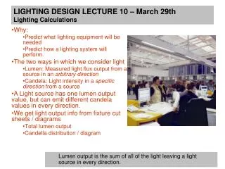
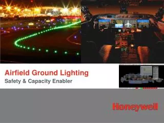
35 th annual Hershey conference. Insulation Resistance Calculations of Airfield Lighting Circuits. Joseph Vigilante, PE. Presentation Objective. To develop a formula to calculate insulation resistance for an airfield lighting circuit and provide theoretical and real-life examples.

E N D
35th annual Hershey conference Insulation Resistance Calculations of Airfield Lighting Circuits Joseph Vigilante, PE
Presentation Objective To develop a formula to calculate insulation resistance for an airfield lighting circuit and provide theoretical and real-life examples.
Presentation Agenda • Cable insulation resistance (IR) background • FAA IR guideline recommendations • Formula development • Airfield lighting circuit calculations • Summary • Open Q&A
Anatomy of insulation current flow • Capacitance charging currents, C • Absorption current, RA • Conduction current, RL Circuit model S DC VOLTAGE SOURCE C RL RA
Anatomy of insulation current flow CAPACITANCE CHARGING CURRENT
Anatomy of insulation current flow CAPACITANCE CHARGING CURRENT ABSORPTION CURRENT
Anatomy of insulation current flow CAPACITANCE CHARGING CURRENT ABSORPTION CURRENT CONDUCTION CURRENT
Anatomy of insulation current flow CAPACITANCE CHARGING CURRENT TOTAL CURRENT ABSORPTION CURRENT CONDUCTION CURRENT
Types of insulation resistance testing Short-time/spot reading VALUE READ AND RECORDED MEGOHMS VALUES CHARTED MEGOHMS 0 TIME 60 sec TIME (MONTHS)
Types of insulation resistance testing Time-resistance method INSULATION PROBABLY OK MEGOHMS INSULATION SUSPECT 0 TIME 10 Min
Testing airfield lighting circuits • AC 150/5340-30F, Design & Installation Details for Airport Visual Aids - Chapter 12, Equipment & Material, Section 13, Testing • 50MΩNon-grounded series circuits • FAA-C-1391, Installation & Splicing of Underground Cable
Resistance values for maintenance • AC 150/5340-26B, Maintenance of Airport Visual Aid Facilities • Suggested minimum values • 10,000 ft. or less - 50MΩ • 10,000 ft. – 20,000 ft. - 40MΩ • 20,000+ ft. - 30MΩ
FAA-C-1391 Installation & Splicing of Underground Cables • Spot Test • Take readings no less than 1 minute after readings stabilized • Cable IR values = 50MΩ, 40MΩ &30MΩ • Loop IR reduced due to parallel summation • Cable IR never less than above values
Insulation resistance formula • Constant current series lighting circuit • Provides for parallel summation of circuit components • 3 components • L-824 cable • L-823 cable connectors • L-830 isolation transformers I RT RN RC V
FAA minimum IR values • L-824 cable • AC 150/5345-7E, Specification for L-824 Underground Electrical Cable for Airport Lighting Circuits • Table 1, Test #9 > ICEA S-96-659, Section 7.11.2 • Corresponding to IR Constant 50,000 MΩ - k-ft. at 15.6°C
FAA minimum IR values • L-823 cable connectors • AC 150/5345-26D, FAA Specification for L-823 Plug and Receptacle, Cable Connectors • Section 5.1 – Type I Connectors 75,000 MΩ
FAA minimum IR values • L-830 isolation transformers • AC 150/5345-47C, Specification for Series to Series Isolation Transformers for Airport Lighting Systems • Table 3 Insulation Resistance 7,500 MΩ
Base formula 1/IR = 1/RC + 1/RN + 1/RT I IR RT RN RC V
Cable equation The insulation resistance of cable for a certain length can be calculated by the following formula: Where: • RC = Insulation resistance in Megohms of cable • K = Specific IR in Megohms - k ft at 60˚ F of insulation • D = Outer diameter of insulation • d = Outer diameter of bare copper wire • L = Length of airfield cable in feet Value of K for EPR insulation = 50,000 Megohms
Cable equation CONDUCTOR JACKET INSULATION d D D= 9.18 mm d= 4.58 mm OD
Cable equation RC = 50,000 MΩ-k ft * Log ( 9.18/4.58) * (1,000/L) RC = 15,098,860 MΩ / L
Connector equation The insulation resistance of L-823 connector splices can be calculated by the following formula: RN = Rc/Nc Where: • RN = Insulation resistance in Megohms of all connectors • Rc = Insulation resistance of L-823 connector splice • Nc = Quantity of L-823 connector splices RN = 75,000MΩ/Nc
Isolation transformer equation The insulation resistance of L-830 isolation transformers can be calculated by the following formula: RT = Rt/Nt Where: • RT = Insulation resistance in Megohms of all transformers • Rt = Insulation resistance of L-830 isolation transformers • Nt = Quantity of L-830 isolation transformers RT = 7,500MΩ/Nt
Base formula 1/IR = 1/RC + 1/RN + 1/RT MΩ⁻¹ I RT RN RC V IR
Developing IR calculation formula L-830 Isolation Transformer L-823 Connector Section 1 Section 2 Supply Return L-824 Series Lighting Cable Section 3
Developing IR calculation formula L-830 Isolation Transformer L-823 Connector Section 1 Section 2 Insulation Resistance to Earth Earth Ground L-824 Series Lighting Cable Section 3
Developing IR calculation formula L-823 Connector Supply L-824 Series Lighting Cable Insulation Resistance to Earth Earth Ground MΩ⁻¹
Developing IR calculation formula L-823 Connector L-830 Isolation Transformer MΩ⁻¹ Insulation Resistance to Earth L-824 Series Lighting Cable Earth Ground
Developing IR calculation formula MΩ⁻¹ Earth Ground Insulation Resistance to Earth L-823 Connector Return L-824 Series Lighting Cable
Developing IR calculation formula MΩ IR total IRsection 2 IRsection 1 IRsection 3
Calculation example Vault CCR SECTION 1 SECTION 2 SECTION 3 Handhole Handhole
Calculation example Section 1: Cable = 5,000 feet Connectors = 2 Isolation XFMRs = 0 Section 2: Cable = 20,500 feet Connectors = 224 Isolation XFMRs = 112 Section 3: Cable = 5,000 feet Connectors = 2 Isolation XFMRs = 0
Calculation Example Section 1: Cable = 5,000 feet Connectors = 2 Isolation XFMRs = 0 CCR Vault Handhole Handhole =
Calculation Example Section 2: Cable = 20,500 feet Connectors = 224 Isolation XFMRs = 112 = .
Calculation Example Section 3: Cable = 5,000 feet Connectors = 2 Isolation XFMRs = 0 CCR Vault Handhole Handhole =
Calculation Example IR total= 50 MΩ Circuit length is 30,500 ft, so the circuit IR is well over the recommended minimum value.
Modifying a circuit Vault CCR SECTION 1 SECTION 2 SECTION 3 Handhole Handhole
Modifying a circuit Each circuit modification warrants a reevaluation of the IR for that circuit Assume: Segment 1: Cable = 5,000 feet Connectors = 2 Isolation XFMRs = 0 Segment 2: Cable = 20,500 feet Connectors = 430 Isolation XFMRs = 215 Segment 3: Cable = 5,000 feet Connectors = 2 Isolation XFMRs = 0 Total circuit: IRsection1 = 2,795 MΩ IRsection3 = 2,795 MΩ IRsection2: RC = 50,000 * Log ( 9.18/4.58) * (1,000/L) = 15,098,860/20,500 =755 MΩ RN = 75,000/Nc = 75,000/430 = 174 MΩ RT = 7,500/Nt = 7,500/215 = 35 MΩ IRsection2 = 1/(1/755 + 1/35 + 1/174) IRsection2 = 28 MΩ IR = 1/ ( 1/2,795 + 1/28 + 1/2,795 ) IR = 27.4 MΩ
Modifying a circuit Total circuit IR = 27.4 MΩ Circuit Length = 30,500 feet Recommended value for +20k feet circuit = 30 MΩ If you remove the transformer component, the circuit IR = 128 MΩ
Case study example: Measuring IR of a TDZ Circuit Total circuit IR = 33.2 MΩ Circuit Length = 16,430 feet 10k-ft – 20k-ft = 40 MΩ W/O Transformers; IR = 164.3 Measured value = 58.10 MΩ Section 1: Cable = 1,615 feet Connectors = 5 Isolation XFMRs = 0 Section 2: Cable = 13,200 feet Connectors = 365 Isolation XFMRs = 180 Section 3: Cable = 1,615 feet Connectors = 5 Isolation XFMRs = 0
Case study example: Measuring IR of a REL Circuit Total circuit IR = 61.6 MΩ Circuit Length = 30,857 feet + 20k-ft = 30 MΩ Measured value = 998 MΩ Section 1: Cable = 1,540 feet Connectors = 5 Isolation XFMRs = 0 Section 2: Cable = 27,777 feet Connectors = 180 Isolation XFMRs = 90 Section 3: Cable = 1,540 feet Connectors = 5 Isolation XFMRs = 0
Summary • Good engineering practice to perform circuit load and insulation resistance calculations • Best practice – establish field test baseline and track results • Standards provide recommended values - reductions are allowed • Check & verify transformers, connectors and cable types and sizes • Minimum allowable component values – higher factory test values • High initial field value does not necessarily indicate a good circuit