Download
1 / 45
470 likes | 763 Vues
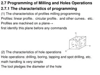
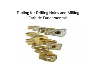
Tooling for Drilling Holes and Milling Carbide Fundamentals. Introduction Selecting of tools Tool size and shape Tool grade and materials Inserts T ool wear ( Causes and consequences ). Objectives. Cutting tools are subjected to: Extremely severe friction.

E N D
Introduction Selecting of tools Tool size and shape Tool grade and materials Inserts Tool wear (Causes and consequences) Objectives
Cutting tools are subjected to: • Extremely severe friction. • Metal-to-metal contact between chip and work-piece. • Metal-to-metal contact resulting in high stress at high temperatures. • During machining, cutting tools remove material from the component to achieve the required shape, dimension and surface roughness (finish). Introduction
Wear occurs during the cutting action, ultimately resulting in the failure of the cutting tool. • When the tool wear reaches a certain extent, the tool or active edge has to be replaced to guarantee the desired cutting action.
Tools • Drills: _ Drills, Center Drills • Boring • Reaming • Tapping • Counter boring • Counter sink 2. End mill 3. Face Mill 4. Slit Mill http://www.youtube.com/user/GlacernMachineTools?feature=pyv&ad=3979815043&kw=manufacturing#p/u/0/om6GQKfoS1g
Chip & Chip Thickness • Type I: Discontinuous chip; segmented, fragmented, highly stressed • Type II: Continuous chip deformation of material with low tensile properties. • Type III: Continuous chip with built-up edge; high tensile material makes spring shape chips. Coolant: • Oil Base • Water Base • Semi syntactic • Full Syntactic
Tool Feed RPM, IPM,IPR, IPT,ACT Example: A 3 in. diameter end mill with 5teethis to machine a 1.125”widthof cut to a square shoulder. A chip load of .006ipt. and a spindle rpm of 400are recommended. Determine if corresponding feed rate needs to be adjusted to maintain chip thickness of .008”.
Feeding Direction For Milling Operation 1. Climb Milling • Should be fed in the direction of cutter rotation. • Causes the tool to make maximum thickness chip at the start of cut and minimum thickness at the end of cut inside the material. • Less clamping and horse power needed. • Climb mill is recommended for thin parts. • Cutting tool has longer life.
2. Conventional Mill • Requires more fixture hold-down force. • Recommended for casting and forging material and hot rolled steel. • Has high tool impact load and excessive tool wear on hard materials.
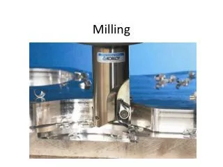
Mill http://www.youtube.com/user/GlacernMachineTools?feature=pyv&ad=3979815043&kw=manufacturing#p/u/0/3SUQKGu7F5w
Insert shape • Geometric features • Lead angle • Type of operation • Maximum number of cutting edges • Strength needed to do the job Selecting an Insert:
INSERT SIZE The size of the insert is based on the inscribed circle*. * (The largest circle that will fit inside the insert.)
Shape of Inserts The shape of the insert will have a great effect on the strength of the tool.
Lead or cutting edge angle: - the angle at which the cutting tool enters the work
Cutting Edge Rake angle: • The angle at which the chips flow away from the cutting edge. • Principle rake angles are: • Positive rake • Negative rake • Natural rake
Provide more support for cutting edge of inserts. Neutral rake has twice as many cutting edges as positive rake. Positive rake should be used when machining soft material because chips are able to flow away from the cutting edge.
TOOL NOSE RADIUS • The nose radius of the tool directly affects tool strength and surface finish as well as cutting speed and feeds. • The larger the nose radius, the stronger the tool is. • The greater the nose radius, the greater the degree of roundness at the tip. • Nose Radius affect : - Tool strength - Surface finish - Cutting speed and feed
In the(P/M) process, metal powders are compacted into desired and often complex shapes and heated without melting to form a solid piece. The powder must be fed properly into the die cavity, and proper pressures must be developed throughout. Inserts
Compaction • Blended powders are pressed into various shapes in dies. • The purposes of compaction are to obtain the required shape, density, and particle-to-particle contactas well as to make the part sufficiently strong for further processing.
Sintering • The process that compact samples are heated in a controlled-atmosphere furnace to a temperature below the melting point. • The principle variables in sintering are temperature, time, and the furnace atmosphere. • Sintering temperatures are generally within 70 to 90% of the melting point of metal or alloy. • https://www.youtube.com/results?search_query=powder+metalorg&oq=powder+metalorg&gs_l=youtube.12...9364.26167.0.34294.17.13.1.3.3.0.299.1924.2j9j2.13.0...0.0...1ac.1.bAKIXvXoM5M
INFILTRATION • Infiltration is accomplished by placing a lower melting “slug” on or beneath the part prior to entering the sintering furnace. • When this secondary part melts, it is absorbed into the pores of the part by capillary action and is diffused into the particles of the primary metal.
IMPREGNATATION • The inherent porosity of P/M components can be utilized by impregnating them with a fluid. • Bearings and bushings that are lubricated internally with up to 30% oil by volume are made by immersing the sintered bearing in heated oil. • The container is then placed in a vacuum chamber, and the air is removed from the pores, being replaced by the lubricant.
Examples of Powder-Metallurgy Techniques (a) balls for ball-point pens (b) automotive components such as piston rings, connecting rods, brake pads, gears, cams, and bushings (c)inserts (tool steels, tungsten carbides) (d) graphite brushes impregnated with copper for electric motors (e) surgical implants
CARBIDE TOOL GRADE • Carbide Tools come in a variety of grades. • The grade is based on carbide wear resistance and toughness. • As insert becomes harder or more wear resistant, it becomes brittle and less tough.
COATING OF CARBIDE INSERTS: • Carbide is a very hard , durable cutting tool, but it has wear. The wear resistance of carbide can be increased by using coatings. • The most common type of coating includes: • Titanium carbide(TiC) • Titanium nitride (TiN) • Aluminum oxide (AlO) • Ceramic • Diamond – coated Inserts (PCD)
Tool Wear • The type of wear depends on the nature of the tool, machined material, cutting conditions, and the type of cutting (turning or milling). • change of shape and size of tools from its original shape. • thermal phenomena in the high speed cutting process cause physical–chemical phenomena which causes tool wear. • tool materials must have good hardness properties.
Crater Wear Build up edge Chipping Cutting edge wear Flank Wear Thermal and Mechanical failure Edge Deformation Notch wear Ultimate Failure Tool Wear
Crater Wear • Diffusion, decomposition and abrasive wear. • Hot chips decompose the cobalt and dissolve the coating. • The soft cobalt wears out of the matrix, the carbide grains no longer have any adhesion and therefore break off. • Crater wear occurs when the binder is being replaced by the material you are cutting
Two criteria are currently used to evaluate the level of crater wear of a tool • The first is the depth of the crater KT • the second is the distance between the cutting edge and the crater KM. • the volume of the crater, the width of the crater and the roughness of the crater.
Crater Wear • Select a more wear resistant insert grade . • Change the chip breaker geometry. • Use coolant. • Reduce the cutting speed and feed
Built-Up Edge • Material adhesion at a high pressure and low temperature, • The work piece material sticks to the cutting edge. • This built-up edge breaks off and takes pieces of the coating of insert with it. • Possible solutions • Increase the cutting speed. • Use coolant • Increase the feed • insert with a sharper cutting edge geometry
Chipping • Abrasive wear and local stress concentration. • Hard micro inclusions in the work-piece material cause local stress concentration. • Possible solutions • Increase the cutting speed. • Reduce the feed • Reduce the risk of vibrations. (The entrance or exit). • Select a stronger cutting edge geometry • Select a tougher grade
Cutting edge wear • Mechanical and thermal overloading. • The heat softens the insert structure. • As the cobalt softens and the insert becomes deformed. • Possible solutions • Reduce the cutting speed. • Reduce the feed. • Use coolant. • Select a more wear Resistant insert • Select an insert with larger nose radius
Flank Wear • Abrasive wear. • Hard micro inclusions in the work-piece cut into the insert. • Small pieces of coating break off and also cut into the insert. • The soft cobalt wears out of the matrix, the carbide grains no longer have any adhesion and therefore break off
Thermal/Mechanical Failure • Rapid change in the thermal load. • Temperature differences between warm and cold zones cause thermal stress. • Fatigue leads to cracking. • Possible solutions • Use an abundant supply of coolant. • Reduce the cutting speed. • Reduce the feed. • Select a tougher hard insert grade. • Use a different machining method • (ratio between time in cut • and time out of cut).
Edge Deformation • Mechanical and thermal overloading. • The heat softens the insert structure. • The cobalt softens and the insert becomes deformed.
Notching • Oxidation (machining surface) and local stress concentration because of Surface hardening (previous cut) • Hard micro inclusions in the work-piece material cause a notch where the work-piece comes into contact with the cutting edge • Select a more wear resistant insert grade(oxidation). • Reduce the cutting speed (oxidation). • Reduce the feed(oxidation). • Select a tougher insert grade. • Select a smaller entering angle
Chip Hammering • Abrasive wear and mechanical overload. • The chips collide with • the cutting edge and damage it. • Possible solutions • Change the feed. • Change the cutting depth. • Select a different chip-breaker geometry. • Select a tougher insert grade
Mechanical Fracture • Mechanical overload. The combination of mechanical and thermal load is so great that the insert breaks during the first cuts (seconds). • Possible solutions • Reduce the feed. • Reduce the cutting depth. • Select a tougher insert grade. • Select an insert with a chip-breaker geometry for larger feeds. • Select a thicker insert.
Drill • http://www.youtube.com/user/GlacernMachineTools?feature=pyv&ad=3979815043&kw=manufacturing#p/u/0/om6GQKfoS1g • Mill • http://www.youtube.com/user/GlacernMachineTools?feature=pyv&ad=3979815043&kw=manufacturing#p/u/0/3SUQKGu7F5w