Download
1 / 70
700 likes | 885 Vues
2.7 Programming of Milling and Holes Operations 2.7.1 The characteristics of programming (1) The characteristics of profiles milling programming Profiles: linear profile , circular profile , and other curves , etc . Profiles are machined on a plane→

E N D
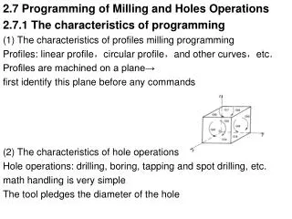
2.7 Programming of Milling and Holes Operations 2.7.1 The characteristics of programming (1) The characteristics of profiles milling programming Profiles: linear profile,circular profile,and other curves,etc. Profiles are machined on a plane→ first identify this plane before any commands (2) The characteristics of hole operations Hole operations: drilling, boring, tapping and spot drilling, etc. math handling is very simple The tool pledges the diameter of the hole
(3) Coordinate system two coordinate systems specified at different locations: • Coordinate system on part drawing. • Coordinate system specified by the CNC. This can be achieved by programming the distance from the current position of the tool to the zero point of the coordinate system.
The positional relation between these two coordinate systems :
(4) Main program and subprogram machining of the same pattern appears at many portions of a program, a program for the pattern is created ↓ Subprogram
Format: M98 P_ L_; M99; e.g. Main program Subprogram O1234 O1111 N10 -----; N10 ----; N20 -----; N20 ----; N30 M98 P1111 L2; N30 ----; N40 ----; --- --- N50 ----; N80 M99; N60 M98 P1111; N70 ----; N80 ----; N90 M30;
(5) The functions of tool compensation tools have different tool length→ length of each tool measured in advance ↓ tool length compensation: setting the difference between the length of the standard tool and the length of each tool a cutter has a radius, the center of the cutter path goes around the workpiece with the cutter radius deviated →cutter radius compensation (radius stored, the tool can be moved by cutter radius apart from the part figure)
2.7.2 Programming codes for milling and holes (1) Absolute and incremental programming (G90, G91) G90 and G91 are used to command absolute or incremental command, respectively • Format: G90 IP__ ; G91 IP__ ;
Instructions: (2) Set up coordinate system G92 • Format:G92 X_Y_Z_; • e.g.:G92 X200.0 Y200.0 Z200.0; G54~G59
(3) Polar coordinate command (G15, G16) The end point coordinate value can be in polar coordinates (radius and angle). Both radius and angle can be absolute or incremental (G90, G91) • The plus direction of the angle is counterclockwise of the selected plane first axis + direction, and the minus direction is clockwise.
An example of bolt hole machining in polar system : Specifying angles and a radius with absolute commands : N1 G17 G90 G16 ; N2 G81 X100.0 Y30.0 Z–20.0 R–5.0 F200.0 ; N3 Y150.0 ; N4 Y270.0; N5 G15 G80 ;
Specifying angles with incremental commands and a radius with absolute commands: N1 G17 G90 G16; N2 G81 X100.0 Y30.0 Z–20.0 R–5.0 F200.0 ; N3 G91 Y120.0 ; N4 Y120.0 ; N5 G15 G80 ;
(4) Scaling (G50, G51) A programmed figure can be magnified or reduced (scaling). The dimensions specified with X_, Y_, and Z_ can each be scaled up or down with the same or different rates of magnification
Scaling along all axes at the same rate of magnification: Scaling along each axes at a different rate of magnification (mirror image)
when a negative magnification is specified, a mirror image is applied If a negative value is set, mirror image is affected
O4003;(main program) • N10 G54 G90 G00 X0 Y0 Z100; • N20 M03 S1000; • N30 G00 X-20 Y10; • N40 Z30 M08; • N50 G01 Z16 F100; • N30 G51 X50 Y30 P0.5; • N40 M98 P1111; • N50 G50; • N60 G00 X-20 Y10; • N70 G01 Z10 F100; • N80 M98 P1111; • N90 G00 Z100; • N100 M05; • N110 M30; • O1111(subprogram) • N10 G42 G01 X0 D01; • N20 X90; • N30 X50 Y90; • N40 X10 Y10; • N50 Y-10; • N60 G40 X-20 Y10; • N70 G00 Z30; • N80 M99;
O9000 ; • G00 G90 X60.0 Y60.0; • G01 X100.0 F100; • G01 Y100.0; • Figure 2.60 Mirroring example • G01 X60.0 Y60.0; • M99; • (Main program) • N10 G00 G90; • N20M98P9000; • N30 G51 X50.0 Y50.0 I–1 J1; • N40 M98 P9000; • N50 G51 X50.0 Y50.0 I–1 J–1; • N60 M98 P9000; • N70 G51 X50.0 Y50.0 I1 J–1 • N80 M98 P9000; • N90 G50;
(4) Coordinate system rotation (G68, G69) A programmed shape can be rotated. When: a workpiece placed with some angle rotated from the programmed position; there is a pattern comprising some identical shapes in the positions rotated from a shape preparing a subprogram of the shape and calling it after rotation
Where in the block G17 (G18 or G19): Select the plane in which contains the figure to be rotated. Α _β_ : specifies the coordinates of the center of rotation for the values specified subsequent to G68 (absolute) R_ : Angular displacement with a positive value indicates counter clockwise rotation The specified angular displacement is considered an absolute or incremental value depending on the specified G code (G90 or G91)
N1 G92 X-5000 Y-5000 G17 ; N2 G68 X7000 Y3000 R60000 ; N3 G90 G01 X0 Y0 F200 ; (G91X-5000Y5000) N4 G91 X10000 ; N5 G02 Y10000 R10000 ; N6 G03 X-10000 I-5000 J-5000 ; N7 G01 Y-10000 ; N8 G69 G90 X-5000 Y-5000 N9 M02 ;
O0068 主程序 • N10 G90 G17 M03 S600; • N20 G43 Z-5.0 H02; • N30 M98 P200; 加工① • N40 G68 X0 Y0 P45; 旋转45° • N50 M98 P200; 加工② • N60 G69; 取消旋转 • N70 G68 X0 Y0 P90; 旋转90° • N80 M98 P200; 加工③ • N90 G49 Z50.0 • N100 G69 M05 M30; 取消旋转 • O200 子程序(①的加工程序) • N110 G41 G01 X20.0 Y-5.0 D02 F300; • N120 Y0; • N130 G02 X30 Y0 I5 J0; • N140 G03 X40 Y0 I5 J0; • N150 X20 Y0 I-10; • N160 G01 Y-6.0 • N170 G40 X0 Y0; • N180 M99;
(5) Reference position • a special position where ↓ the tool is exchanged or the coordinate system is set reference position ( a fixed position, to which the tool can easily be moved by the reference position return function)
① Reference position return check (G27) function which checks whether the tool has correctly returned to the reference position : ( If correctly returned along a specified axis, the lamp for the axis goes on; if not, an alarm is displayed) • Format: G27 IP__ ; (IP: Specifying the reference position (absolute/incremental command)) e.g. G27 X385.612 Y210.812 Z421.226 Note: at rapid traverse rate of each axis→ cutter compensation should be cancelled before this command
② Reference position return (G28) automatically moved to the reference position via an intermediate position along a specified axis Format: G28 IP__ ; ( IP: specifying the intermediate position (Absolute/incremental)) e.g. G90 G54 G28 X300. Y250. ; G91 G28 X100. Y150.; G91 G28 X0 Y0; Note: the cutter compensation, and tool length compensation should be cancelled before this command.
③ Return from the reference position (G29) automatically move from the reference position to a specified position via an intermediate position along a specified axis (G29 is commanded immediately following the G28) Format: G29 IP__ ; ( IP: specifying the destination of return; For incremental programming, specifying the incremental value from the intermediate point )
: M06 T02; G90 G28 Z50.0; M06 T03; G29 X35.0 Y30.0 Z5.0; :
(6) Canned cycles With a canned cycle, a frequently used machining operation can be specified in a single block (make it easier to create programs; shorten the program to save memory)
A canned cycle consists of a sequence of six operations • Operation 1: Positioning of axes X and Y (including also another axis) • Operation 2: Rapid traverse up to point R level • Operation 3: Hole machining • Operation 4: Operation at the bottom of a hole • Operation 5: Retraction to point R level • Operation 6: Rapid traverse up to the initial point
The positioning axis is an axis other than the drilling axis Travel distance along the drilling axis varies for G90 and G91
Return point level G98/G99 (When the tool reaches the bottom of a hole, the tool may be returned to point R (G99) or to the initial level (G98) (Generally, G99 is for the first drilling operation, G98 is for the last operation)
G73, G74, G76, and G81 to G89 are modal G codes →Specify all necessary drilling data at the beginning of canned cycles; when canned cycles are being performed, specify data modifications only. • To repeat drilling for equally–spaced holes, specify the number of repeats in L_. ( Specify the first hole position in incremental mode (G91) ) To cancel a canned cycle, use G80
G81:for normal drilling (drilling, spot drilling) G81 X_ Y_ Z_ R_ F_; X_ Y_: Hole position data Z_ : Bottom data of the hole R_ : Point R level F_ : Cutting feedrate
At the bottom, a dwell is performed G82:for holes more accurately with respect to depth (沉孔,锪孔,阶梯孔) G82 X_ Y_ Z_ R_ P_ F_ (P_ : Dwell time at the bottom of a hole)
G85:for reaming cutting feed is performed to return to point R G85 X_ Y_ Z_ R_ F_
G86:used to bore a hole the spindle is stopped at the bottom of the hole G86 X_ Y_ Z_ R_ F_
G76:for fine boring (When the bottom reached, the spindle stops at a fixed rotation position,and the tool is moved away from the machined surface and retracted) G76 X_ Y_ Z_ R_ Q_ P_ F_ Q_ : Shift amount at the bottom of a hole P_ : Dwell time at the bottom of a hole
Example :Incremental mode for canned cycles (a series of evenly spaced holes along one direction: Program holes incrementally to drastically reduce the number of commands)
O0046; G54 T01 M06; M03 S600; G43 G00 H01 Z20.; X0. Y20. M08; G99 G91 G81 X20. Z-17. R-18. F50. L10; Y20.; (first hole in second row) X-20 L9; (nine holes in second row) Y20. (first hole in third row) X20 L9; (nine holes in third row) … G80 M09; G49 G91 G28 Z0 ; M30;
G73 X_ Y_ Z_ R_ Q_ F_ G73:performs high–speed peck drilling (It performs intermittent cutting feed to the bottom of a hole, while removing chips from the hole) Q_ : Depth of cut for each cutting feed, specified as an incremental value
G83:performs peck drilling (It performs intermittent cutting feed to the bottom of a hole while removing shavings from the hole) G83 X_ Y_ Z_ R_ Q_ F_