Special Milling Operations
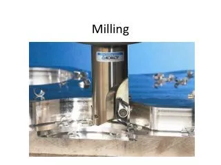
Special Milling Operations. Unit 63. Objectives. Set up and use the rotary table to mill a circular slot Set up and mill internal and external dovetails Jig bore holes on a vertical mill. Vertical Milling Machine. Versatility increased using specially shaped cutters and accessories


Special Milling Operations
E N D
Presentation Transcript
Special Milling Operations Unit 63
Objectives • Set up and use the rotary table to mill a circular slot • Set up and mill internal and external dovetails • Jig bore holes on a vertical mill
Vertical Milling Machine • Versatility increased using specially shaped cutters and accessories • Rotary table accessory permits milling of radii and circular slots • Boring head in spindle and measuring rods on tale allow accurate jig boring of holes
The Rotary Table • Circular milling attachment • Used on plain universal vertical milling machines and slotters • Provide rotary motion to workpiece • Cut radii, circular grooves and circular sections • Two types • hand feed and power feed
Rotary Table Construction • Base bolted to milling machine table • Rotary table fits into base • Worm gear on bottom of rotary table • Worm shaft mounted in base and meshes with and drives worm gear • Handwheel mounted on outer end of worm shaft • Vernier scale on collar permits setting to within 2 minutes of a degree
Rotary Table Construction • T-slots cut into top surface to permit clamping of work • Hole in center of table accommodates test plugs for easy centering of table with machine spindle • Some have indexing attachment instead of handwheel
Indexing Attachment • Serves same purpose as handwheel • Permits indexing of work with dividing head accuracy • Worm and wormwheel ratio not necessarily 40:1 • Other common ratios: 72:1, 80:1, 90:1, 120:1 Example: Calculate indexing for 5 equally spaced holes on a circular plate using a rotary table with an 80:1 ration
Rotary Table with Powerfeed • Worm shaft connected to milling machine lead screw drive gear by special shaft and end gear train • Rate of rotation controlled by feed mechanism of milling machine • Operator control by automatic feed lever or handwheel • Suited for production work and continuous milling of numerous small, identical parts
To Center Rotary Table with Vertical Mill Spindle • Square vertical head with machine table • Mount rotary table on milling machine • Place test plug in center hole • Mount indicator with grasshopper leg in machine spindle • With indicator just clearing top of test plug, rotate machine spindle by handalign plug with spindle
To Center Rotary Table with Vertical Mill Spindle • Bring indicator into contact with diameter of plug and rotate spindle by hand • Adjust machine table by longitudinal and crossfeed handles until dial indicator registers no movement • Lock machine table and saddle, recheck alignment • Readjust if necessary
Using Special Plugs to Center • Problem: work on several identical workpieces that have machined hole in center - need to align • Special plug made to fit center hold of workpiece and hole in rotary table • Once machine spindle aligned with table, each succeeding piece can be aligned quickly and accurately by placing over plug
Method to Center Workpiece on Rotary Table (no plug) • Align rotary table with vertical head spindle • Lightly clamp workpiece to rotary table in approximate center • Do not move crossfeed or longitudinal feed • Disengage rotary table worm mechanism • Mount indicator in machine spindle or on milling machine table
Bring indicator into contact with surface to be indicated and revolve rotary table by hand • With soft metal bar, tap work until no movement registered on indicator in complete revolution of table • Tap away from indicator movement • Clamp workpiece tightly and recheck accuracy of setup Note: If center-punch mark must be aligned, wiggler mounted in milling machine spindle instead of indicator.
Radius Milling Procedure • Align vertical milling machine spindle at 90º to table • Mount circular milling attachment • Center rotary table with machine spindle • Use test plug in table and dial indicator in spindle • Set longitudinal feed dials and crossfeed dial to zero
Mount work on rotary table • Align center of radial cuts with table center • Can use special arbor or wiggler • Move either crossfeed or longitudinal feed an amount equal to radius required • Lock both table and saddle • Mount proper end mill • Rotate work (using handwheel) to starting point of cut • Set depth of cut and machine slot to size
Milling a T-Slot Procedure • Consult handbook for T-slot dimensions • Lay out position of T-slot • Square vertical milling machine spindle with machine table • Mount work on milling machine • Align vise or slot if clamped with table
Mount an end mill having diameter slightly larger than diameter of bolt body • Machine center slot to proper depth of T-slot, using end mill • Remove end mill, mount proper T-slot cutter • Set T-slot cutter depth to bottom of slot • Machine lower part of slot
Milling Dovetails • Used to permit reciprocating motion between two elements of a machine • Composed of external or internal part • Adjusted by means of a gib • Machines on vertical milling machine or horizontal mill with vertical mill attachment • Dovetail cutter • Special single-angle end mill type of cutter ground to angle of dovetail required
Procedure for Milling anInternal Dovetail • Refer to handbook for method • Check measurements of workpiece in which dovetail is to be cut • Remove all burrs • Lay out position of dovetail • Mount workpiece in vise and clamp on rotary table (long work – bolt to table)
Indicate side of workpiece or slot layout to see that it is parallel to line of table travel • Mount end mill of a diameter narrower than center section of dovetail • Start end mill and touch up to side of work, after checking cutter rotation • Set crossfeed dial to zero • Move work over until end mill in center of dovetail • Distance from side of workpiece to center of dovetail plus half diameter of cutter
Lock saddle in position and set crossfeed dial to zero • Touch edge of cutter to top of work • Move work clear of cutter and set depth of cut • Lock knee in position • Depth of slot should be .030 to 0.50 in. deeper than bottom of dovetail • Mill channel to width of cutter
Move work over amount equal to half difference between machined slot size and size of dovetail at top • Take finish cut along one side of work • Check width of slot • Move work over to finished width of top of dovetail (Check for backlash) • Cut second side and check width of slot • Return saddle to zero
Mount dovetail cutter • Set depth for roughing cut • Should be about .005 to .010 in. less than finish depth • Calculate width of dovetail at bottom • Move work over .010 in. less than finished size of this side • Note readings on crossfeed dial • Rough out angle on first side
Move work over to other side the same amount from centerline and rough-cut other side • Set cutter to proper depth • Machine bottom surface (both sides) of dovetail to finished depth • Using two rods, measure dovetail for size
Move table over half the difference between rough dovetail and finished size • Check for backlash • Take finish cut on one side • Move table over required amount, and finish other side • Check finish size of dovetail Note: If work mounted centrally on rotary table, possible torotate work a half-turn (180º) after 18 and take same cuts oneach side of block for each successive step.
Procedure to Mill an External Dovetail • Center cutter over dovetail position • Remove as much material as possible from each side of external dovetail • Cut to largest size of dovetail • Mount dovetail cutter, and center it with workpiece • Move work over ½ width of dovetail plus half diameter of cutter • Allow 0.010 in. for finish cut
Take roughing cut • Move work over equal amount to other side of centerline, taking up backlash • Rough-cut second side • Adjust work over, and take finish cut on one side • Measure dovetail using two rods • Adjust for finish cut on second side and take this cut • Measure width of finished dovetail
Jig Boring on a Vertical Milling Machine • Vertical milling machine does not have same lead screw accuracy as jig borer • Must have some external measuring system • Measuring rods and dial indicators, vernier scale, optical measure devices • Measuring rods come in sets • Both inch precision and metric precision
Measuring Rod Sets • Inch precision end-measuring rods • Supplied in sets of 11 rods hardened • Two micrometer heads capable of measuring 4-5 in to accuracy of .0001 in. • One for longitudinal settings and other for transverse • Lengths of rods: 1, 2, 6 and 12 in rods • Metric precision end-measuring rods • Same set up as inch rods only in mm • Accuracy of 0.002 mm
To Position Milling Machine Table Using Measuring Rods • Set spindle to edge of work • Clean trough and ends of stop rods and indicator rods • Check indicator for free operation • Place required number of rods in trough to take up space between stop rod and indicator rod
Adjust micrometer until extended enough to cause indicator needle to move half-turn • Lock table • Set indicator bezel to zero • Increase rod and micrometer buildup by length of measurement between side of workpiece and hole location • Move table along more than this required distance
Insert rods and micrometer head • Move table back until needle moves half-turn and registers zero • Lock table • Recheck setting and adjust if necessary
Digital Readout Boxes • Electronically controlled measuring devices • Mounted on table and saddle • Indicate table travel to accuracy of .005 or .0001 in. • Digital readout display • Indicates distance traveled through series of numbers visible • Permits quick and accurate setting of machine table in both X and Y axes
Vernier Scale • May be used with milling machine • Mounted adjacent to feed screw collars • Permits reading in .0001 in or 0.002 mm. • Setting must be made in one direction only in order to remove backlash Note: Can position holes without scales by using thegraduated feed collars. This method not as accurate.
Vertical Milling Machine Attachments • Rack milling attachment • Permits machining of racks and broaches on vertical mill • Slotting attachment • Fitted to back end of overarm (180º rotation) • Operates independently of machine drive • Transmits reciprocating motion to single-pointed tool by means of motor-driven eccentric • Used for cutting keyways and slotting out small blanking dies
Die Sinking • One important application of vertical milling machine • Dies used in drop forging and die casting have impressions or cavities cut into them by die sinking • Generally done by hand control of machine • Followed by considerable filing and polishing • Machine equipped with tracer head
Tracer-Controlled Machine • Form of master transferred to workpiece by hydraulic tracer unit actuated by stylus • Contacts master and moves cutter up or down with vertical or side travel of stylus • Work and master fastened to table and travel at same rate • Some machines equipped with ratio devices