Design Methodologies
Design Methodologies. The Design Problem. Source: sematech97. A growing gap between design complexity and design productivity. Design Methodology. Design process traverses iteratively between three abstractions: behavior, structure, and geometry


Design Methodologies
E N D
Presentation Transcript
The Design Problem Source: sematech97 A growing gap between design complexity and design productivity
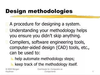
Design Methodology • Design process traverses iteratively between three abstractions: behavior, structure, and geometry • More and more automation for each of these steps
Design Analysis and Verification • Accounts for largest fraction of design time • More efficient when done at higher levels of abstraction - selection of correct analysis level can account for multiple orders of magnitude in verification time • Two major approaches: • Simulation • Verification
Digital Data treated as Analog Signal Circuit Simulation Both Time and Data treated as Analog Quantities Also complicated by presence of non-linear elements (relaxed in timing simulation)
Representing Data as Discrete Entity Discretizing the data using switching threshold The linear switch model of the inverter
Circuit versus Switch-Level Simulation Circuit Switch
Structural Description of Accumulator Design defined as composition of register and full-adder cells (“netlist”) Data represented as {0,1,Z} Time discretized and progresses with unit steps Description language: VHDL Other options: schematics, Verilog
Behavioral Description of Accumulator Design described as set of input-output relations, regardless of chosen implementation Data described at higher abstraction level (“integer”)
Behavioral simulation of accumulator Discrete time Integer data (Synopsys Waves display tool)
Timing Verification Critical path Enumerates and rank orders critical timing paths No simulation needed! (Synopsys-Epic Pathmill)
Issues in Timing Verification False Timing Paths
Custom Design – Layout Editor Magic Layout Editor (UC Berkeley)
Symbolic Layout • Dimensionless layout entities • Only topology is important • Final layout generated by “compaction” program Stick diagram of inverter
Cell-based Design (or standard cells) Routing channel requirements are reduced by presence of more interconnect layers
Standard Cell — Example [Brodersen92]
Standard Cell - Example 3-input NAND cell (from Mississippi State Library) characterized for fanout of 4 and for three different technologies
Automatic Cell Generation Random-logic layout generated by CLEO cell compiler (Digital)
Macrocell Design Methodology Macrocell Interconnect Bus Floorplan: Defines overall topology of design, relative placement of modules, and global routes of busses, supplies, and clocks Routing Channel
Macrocell-Based DesignExample SRAM SRAM Data paths Routing Channel Standard cells Video-encoder chip [Brodersen92]
Gate Array — Sea-of-gates Uncommited Cell Committed Cell(4-input NOR)
Sea-of-gate Primitive Cells Using oxide-isolation Using gate-isolation
Sea-of-gates Random Logic Memory Subsystem LSI Logic LEA300K (0.6 mm CMOS)
Prewired Arrays Categories of prewired arrays (or field-programmable devices): • Fuse-based (program-once) • Non-volatile EPROM based • RAM based
Programmable Logic Devices PAL PLA PROM
EPLD Block Diagram Macrocell Primary inputs Courtesy Altera Corp.
Field-Programmable Gate ArraysFuse-based Standard-cell like floorplan
Interconnect Programming interconnect using anti-fuses
RAM-based FPGABasic Cell (CLB) Courtesy of Xilinx
RAM-based FPGA Xilinx XC4025
Validation and Test of Manufactured Circuits Goals of Design-for-Test (DFT) Make testing of manufactured part swift and comprehensive DFT Mantra Provide controllability and observability Components of DFT strategy • Provide circuitry to enable test • Provide test patterns that guarantee reasonable coverage
Test Classification • Diagnostic test • used in chip/board debugging • defect localization • “go/no go” or production test • Used in chip production • Parametric test • x e [v,i] versus x e [0,1] • check parameters such as NM, Vt, tp, T
Design for Testability Exhaustive test is impossible or unpractical
Problem: Controllability/Observability • Combinational Circuits: controllable and observable - relatively easy to determine test patterns • Sequential Circuits: State! Turn into combinational circuits or use self-test • Memory: requires complex patterns Use self-test
Test Approaches • Ad-hoc testing • Scan-based Test • Self-Test Problem is getting harder • increasing complexity and heterogeneous combination of modules in system-on-a-chip. • Advanced packaging and assembly techniques extend problem to the board level
Generating and Validating Test-Vectors • Automatic test-pattern generation (ATPG) • for given fault, determine excitation vector (called test vector) that will propagate error to primary (observable) output • majority of available tools: combinational networks only • sequential ATPG available from academic research • Fault simulation • determines test coverage of proposed test-vector set • simulates correct network in parallel with faulty networks • Both require adequate models of faults in CMOS integrated circuits
a, g : x1 sa1 • b : x1 sa0 or • x2 sa0 • g : Z sa1 Fault Models • Most Popular - “Stuck - at” model Covers almost all (other) occurring faults, such as opens and shorts.
Problem with stuck-at model: CMOS open fault Sequential effect Needs two vectors to ensure detection! Other options: use stuck-open or stuck-short models This requires fault-simulation and analysis at the switch or transistor level - Very expensive!
Problem with stuck-at model: CMOS short fault Causes short circuit between Vdd and GND for A=C=0, B=1 Possible approach: Supply Current Measurement (IDDQ) but: not applicable for gigascale integration
Path Sensitization Goals: Determine input pattern that makes a fault controllable (triggers the fault, and makes its impact visible at the output nodes) sa0 1 Fault enabling 1 1 1 1 1 0 Fault propagation 0 Techniques Used: D-algorithm, Podem
Ad-hoc Test Inserting multiplexer improves testability
Polarity-Hold SRL (Shift-Register Latch) Introduced at IBM and set as company policy