High-Current Polarized Source Developments
This document explores the ongoing developments in high-current polarized electron sources at MIT, crucial for projects like eRHIC. It covers the requirements of the Electron-Ion Collider (EIC), the advancements at MIT-Bates, and specific innovations such as RF gun designs. Key challenges include achieving high average currents, managing heat loads on cathodes, and addressing ion damage. The report details experimental results, the design of a new cathode cooling system, and simulations aimed at optimizing beam performance. Insights into lifetime improvement strategies and laser power requirements are included. ###

High-Current Polarized Source Developments
E N D
Presentation Transcript
High-Current Polarized Source Developments Evgeni Tsentalovich MIT
OUTLINE • Introduction, motivation • EIC requirements • Developments at MIT-Bates • RF gun developments • Conclusion
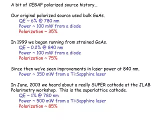
Luminosity ~ I(average) ~ 250 mA I(peak) ~ 100 A High polarization → strained GaAs → QE ~ 0.5% eRHIC (Linac-ring version) Polarized electron source with an extremely high current – crucial element of the project Average laser power ~ 80 W (fresh crystal) Hundreds Watts might be needed as crystal loses QE
Solution: Cathode with very large area High peak current – surface charge saturation (QE drops at high light intensity); space charge saturation Main challenges High average current – cathode damage by ion bombardment High heat load on the cathode – tens of Watts of laser power
High Average Current • Average current of tens or even hundreds of mA is required • Modern state-of-the-art guns produce ~100-200 A • Average current of ~ 1 mA achieved in tests at JLab and Mainz; lifetime ~ 20 h • Average current of up to 10 mA achieved at Mainz with very short lifetime (needs active cathode cooling) Main problem – ion backbombardment
anode residual gas cathode Ionized residual gas strikes photocathode Ion damage distributed over larger area Ion Damage Ion damage is inversely proportional to emitting area
JLAB data Laser spot Damage groove Cathode Damage location Electrons and ions follow different trajectories. Usually, ions tend to damage central area of the cathode. Ring-like cathodes ?
Ion Trapping in CW Beam Cathode Beam line Anode Ions produced below the anode are trapped in the electron beam. Half of them will drift toward the gun and get accelerated in the cathode-anode gap toward the crystal.
High Intensity Gun Studies at MIT/Bates • The project investigates the feasibility of extracting very high (tens, perhaps hundreds of mA) current from the gun. • The project addresses issues of high average current and high heat load on the cathode. • Phase I – studies of ion damage, design and construction of the cathode cooler, gun simulations. • Phase II – design and construction of the gun and the beam line, beam tests.
Ion Damage Studies - Apparatus • Existing gun. • New diode array laser (~808 nm, P up to 45 W). • Existing test beam line. This beam line was not designed for high current and beam losses of 5-10% are typical. These losses produce out-gassing, and reduce the lifetime by both poisoning the cathode and ion bombardment. Relatively low lifetime and significant ion damage allowed to conduct the measurements fast. • CW current – one can expect ion trapping.
Ring-shaped Laser Beam Fiber L1 Axicon L2 Cathode Axicon (conical lens) in combination with a converging lens (L2) produces ring-shaped beam in the focal plane of L2. Lens L1 reduces the laser beam divergence (25 from the fiber). Without axicon, a very small beam spot will be produced. QE could be mapped by moving the L2
Axicon-based System Simulations L1 Axicon L2
Beam Profile (no axicon) FWHM<.5 mm
QE change (small spot in the center) Run 12.32 C
QE change (run with axicon) Run 17.35 C
QE change (axicon, anode biased 1 kV) Run 17.62 C
QE change (large spot in the center) Run 17.46 C
QE change (small spot in the corner) Run 16.84 C
High Intensity Run (1 mA) • Achieved .5 mA with laser power of .25 W (QE=.34 %) • Achieved 1 mA with laser power of 1.16 W (QE=.15%) • Gun vacuum pressure rise (factor of 10) • Current dropped to 132 A in 1 hour • At laser power of 1.16 W, QE degrades even without HV ! – Overheating. • Thermal estimate (thermal conductivity through the stalk only ~.01-.025 W/degree
Conclusion • Ion damage is concentrated near the center of the cathode in every configuration. • Ring-shaped beam allows to improve the lifetime significantly. • Biasing the anode improves the lifetime of the CW beam. • Active cooling is a “must” for laser powers exceeding 1 W.
New optics Old optics: Small spot Axicon New optics
Gun Simulation • Large emitting area produces large emittance • Although emittance is less important for eRHIC, large beam could result in beam losses near the gun. • The main purpose of the simulations is to minimize the beam losses in the gun and beam line. • The second goal – ion distribution optimization
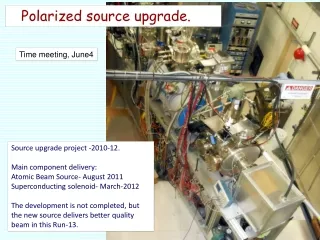
Cathode Cooling • The conceptual design of the test chamber is completed. • The test chamber will validate the adequacy of the cooling power, HV and high vacuum compatibility and vacuum cathode handling with manipulators.
Cathode Cooling HV Water in Water out Manipulator Crystal Cathode Laser
DBR – Equipped Crystal “Normal” cathode Cathode with Distributed Bragg Reflector (DBR) In “normal” cathode, only 30% of light is reflected. In DBR-equipped cathode 99% of light is reflected.
Polarized RF guns • No positive results as yet, and very few attempts. • Very high average current is not expected. • Main advantages – high brightness, low emittance, high electron energy. High peak current could be achieved. • Several normal-conducting RF gun projects are under way (SLAC, JLAB). High Order Mode (HOM) and Plane Wave Transformer (PWT) concepts are used. These concepts allow improved vacuum conditions. • BNL develops Superconducting RF gun. Two versions are under way.
Conclusion Very significant results are expected in the next couple of years !