Software Modeling
Software Modeling. Jerry Lebowitz. Software Modeling. Topics. Why software models Unified modeling language (UML ) UML structure diagrams Class diagrams UML behavior diagrams State diagrams Interaction diagrams Use cases Activity diagrams. Why Models.


Software Modeling
E N D
Presentation Transcript
Software Modeling Jerry Lebowitz
Topics • Why software models • Unified modeling language (UML) • UML structure diagrams • Class diagrams • UML behavior diagrams • State diagrams • Interaction diagrams • Use cases • Activity diagrams
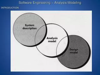
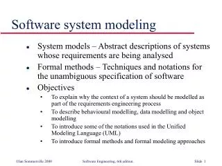
Why Models • Models help one understand and shape both the problem and the solution • It is a simplification of a complex system
Unified Modeling Language (UML) • UML is a graphical language for visualizing, specifying, constructing and documenting the artifacts of an object-oriented software intensive system • Standards based • UML is a common language to express models • It does not tell one how to develop software
UML Structure Diagrams • Structure diagrams emphasize the things that must be present in the system being modeled • Class diagram: describes the structure of a system by showing the system's classes, their attributes, and the relationships among the classes • Component diagram: describes how a software system is split up into components and shows the dependencies among these components • Composite structure diagram: describes the internal structure of a class and the collaborations that this structure makes possible • Deployment diagram: describes the hardware used in system implementations and the execution environments and artifacts deployed on the hardware • Object diagram: shows a complete or partial view of the structure of an example modeled system at a specific time
Class Diagrams • Class diagrams are the main building blocks of object oriented modeling • Used for data modeling • Classes are represented with boxes which contain three parts • The top part contains the name of the class • The middle part contains the attributes of the class • The bottom part gives the methods or operations the class can take or undertake
Class Diagram Visibility • "+" Public • "-" Private • "#" Protected • "/" Derived (can be combined with one of the others) • "_" Static
Relationships - Inheritance • Indicated by a solid line with a closed, unfilled arrowhead pointing at the super class
Relationships - Composition • Draw a solid line from the parent class to the part class, and draw an unfilled diamond shape on the parent class's association end
UML Behavior Diagrams • Emphasize what must happen in the system being modeled • Activity diagram: describes the business and operational step-by-step workflows of components in a system. An activity diagram shows the overall flow of control • UML state machine diagram: describes the states and state transitions of the system • Use Case Diagram: describes the functionality provided by a system in terms of actors, their goals represented as use cases, and any dependencies among those use cases
UML State Diagram • Directed graphs in which nodes denote states and connectors denote state transitions .
State Diagram • A state is denoted by a round-cornered rectangle with the name of the state written inside it • Initial and final states • The initial state is denoted by a filled black circle and may be labeled with a name • The final state is denoted by a circle with a dot inside and may also be labeled with a name
State Diagram • Transitions • Transitions from one state to the next are denoted by lines with arrowheads • A transition may have a trigger, a guard and an effect • "Trigger" is the cause of the transition, which could be a signal, an event, a change in some condition, or the passage of time. • "Guard" is a condition which must be true in order for the trigger to cause the transition • "Effect" is an action which will be invoked directly on the object that owns the state machine as a result of the transition.
State Diagram • The diagram below shows a state with an entry action and an exit action
Interaction Diagrams • Emphasize the flow of control and data among the things in the system being modeled: • Communication diagram: shows the interactions between objects or parts in terms of sequenced messages. They represent a combination of information taken from Class, Sequence • Use Case Diagramsdescribes both the static structure and dynamic behavior of a system • Interaction overview diagram: provides an overview in which the nodes represent communication diagrams • Sequence diagram: shows how objects communicate with each other in terms of a sequence of messages. Also indicates the lifespans of objects relative to those messages • Timing diagrams: a specific type of interaction diagram where the focus is on timing constraints
Use Case Definitions (1) • Use case • A sequence of actions a system performs that yields an observable result of value to an actor or actors • Iterative and evolutionary nature • Good fit for agile development • A solution can be expressed as a set of use cases • Derived from system requirements • Actor • Someone or something outside the system that interacts with the system
Use Case Definitions (2) • Actions • A computational or algorithmic procedure that is invoked when an actor provides a signal to the system or when the system gets a time event • The execution of an action represents some transformation or processing in the system • A sequence of actions • Specific flow of events through the system
Use Case Definitions (3) • An observable result of value • The sequence of actions must yield something that has value to an actor of the system • An actor should not have to perform multiple use cases to achieve something useful
Use Case Development • Create the "Sunny Day" use cases • Use cases that are most likely going to occur when all goes well • Create the “Raining Day" use cases • Use cases that are most likely going to occur when do not go well
Use Case Development • Identify the key components of your use cases • Textual representation illustrating a sequence of events
Example Use Case for ATM Transfer Money Use cases : Shown as circles or ovals Withdraw Money Check Balance Client
Use Case Name : Withdraw Funds • Summary : Customer uses a valid card to withdraw funds from a valid bank account • Actor : ATM Customer • Precondition : ATM is displaying the idle welcome message • Description : • Customer inserts an ATM Card into the ATM Card Reader • If the system can recognize the card, it reads the card number • System prompts the customer for a PIN • Customer enters PIN • System checks the card’s expiration date and whether the card has been stolen or lost • If the card is valid, the system checks if the entered PIN matches the card PIN • If the PINs match, the system finds out what accounts the card can access • System displays customer accounts and prompts the customer to choose a type of transaction
Use Case Name : Withdraw Funds • The previous eight steps are part of all three use cases • The following steps are unique to the Withdraw Funds use case • Customer selects Withdraw Funds, selects the account number, and enters the amount • System checks that the account is valid, makes sure that customer has enough funds in the account, makes sure that the daily limit has not been exceeded, and checks that the ATM has enough funds • If all four checks are successful, the system dispenses the cash • System prints a receipt with a transaction number, the transaction type, the amount withdrawn, and the new account balance • System ejects card • System displays the idle welcome message Transfer Money Check Balance Withdraw Money Client
Use Case Name : Withdraw Funds • Alternatives : • If the system cannot recognize the card, it is ejected and the welcome message is displayed • If the current date is past the card's expiration date, the card is confiscated and the welcome message is displayed • If the card has been reported lost or stolen – stolen, it is confiscated and the welcome message is displayed • If the customer entered PIN does not match the PIN for the card, the system prompts for a new PIN • If the customer enters an incorrect PIN three times, the card is confiscated and the welcome message is displayed • If the account number entered by the user is invalid, the system displays an error • message, ejects the card and the welcome message is displayed • If the request for withdraw exceeds the maximum allowable daily withdrawal amount, the system displays an apology message, ejects the card and the welcome message is displayed • If the request for withdraw exceeds the amount of funds in the ATM, the system displays an apology message, ejects the card and the welcome message is displayed • If the customer enters Cancel, the system cancels the transaction, ejects the card and the welcome message is displayed • Postcondition : • Funds have been withdrawn from the customer’s account Transfer Money Check Balance Withdraw Money Client
Extended Relationships • One can use an extend relationship to specify that one use case (extension) extends the behavior of another use case (base) • One can add extend relationships to a model to show the following situations • A part of a use case that is optional system behavior • A sub-flow is executed only under certain conditions
Sample Graphical Use Case See example
User Stories versus Use Cases • A User Story is the prelude to the use case by stating the need before the use case tells the story
Activity Diagrams • Activity diagrams are graphical representations of workflows • Intended to model both computational and organizational processes • Shows the overall flow of control
Activity Diagrams • Activity diagrams are constructed from a limited number of shapes, connected with arrows (like a flowchart) • Rounded rectangles represent actions • Diamonds represent decisions • Bars represent the start (split) or end (join) of concurrent activities • A black circle represents the start (initial state) of the workflow • An encircled black circle represents the end (final state) • Arrows run from the start towards the end and represent the order in which activities happen
Use Cases to Activity Diagrams • Use case descriptions become action state nodes in the activity diagram • Alternatives are sequential branch nodes