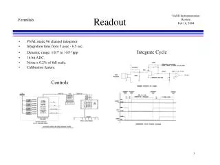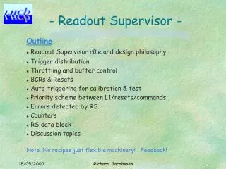
Readout Chain
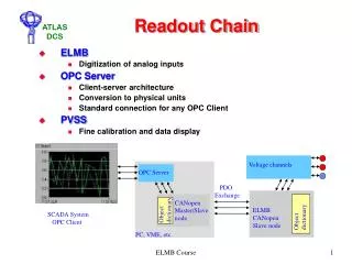
Voltage channels. OPC Server. PDO Exchange. CANopen Master/Slave node. Object dictionary. Object dictionary. ELMB CANopen Slave node. SCADA System OPC Client. PC, VME, etc. Readout Chain. ELMB Digitization of analog inputs OPC Server Client-server architecture

Readout Chain
E N D
Presentation Transcript
Voltage channels OPC Server PDO Exchange CANopen Master/Slave node Object dictionary Object dictionary ELMB CANopen Slave node SCADA System OPC Client PC, VME, etc. Readout Chain • ELMB • Digitization of analog inputs • OPC Server • Client-server architecture • Conversion to physical units • Standard connection for any OPC Client • PVSS • Fine calibration and data display ELMB Course
Typical Application • ELMB • Maximum of 32 ELMBs in a branch • Kvaser PCI card (2 or 4 port) • CANbus cable from USA15 or US15 to UX15 • TIS qualified • Shielded • Length ≈ 150m • Including remote powering, 7 lines: • GND • CAN signals • CAN power (20 mA/ELMB) • Digital + Analog power (15 + 9 mA/ELMB) • CAN Power Crate or commercial Power Supply • Patch panel • Rack (and wall) mounted ELMB motherboard ELMB Course
Rack Mounted ELMBs s ~ 5 m s ~ 0.5 m Physical Distribution Kvaser PCI-CAN PS USA15 UX15 Patch Panel ELMB Course
The CAN Bus • Each node must have a unique ID • 0 reserved; applies to all nodes in the CANbus • Both ends of bus must be terminated • 120 ohm resistor between CAN_H and CAN_L • Straight Bus configuration • Star or Ring configurations are not possible • Maximum of 63 ELMBs per bus • Recommended maximum of 32 per bus • Configurable baud rate • Faster rates restrict bus length • 125 Kbaud ≈ 500m • 250 Kbaud ≈ 270m ELMB Course
Node ID DIP switches The ELMB(Embedded Local Monitor Board) • General purpose CAN node using CANopen • Flexible I/O functions • Multiplexed ADC, 16 bit, 64 channels with signal adaptation. Configurable for rate, range, mode and number of channels • 8 input, 8 output and 8 definable I/O ports • SPI bus • Low power consumption, opto-isolated • Add-ons: DAC, 12 bit, 16-64 channels Interlock facility • Data sent periodically, on-request or on-change • Radiation tolerant • 0.5 Gy and 3*1010 neutrons per year • Operation in field of 1.5 Tesla • Remote diagnostics and loading of SW • SEE detection and recovery ELMB Course
ELMB Motherboard • General purpose motherboard • Allows for signal adaptation • Connectors for analog and digital input and outputs • Power connector • CAN bus connector ELMB Course
Motherboard Bottom Side ELMB Course
Adapters • Temperature sensors – 2 wire • For NTC 10K or PT1000 • Temperature sensors – 4 wire • For PT100 • Differential voltage attenuator • Attenuates 1:100 • Inline resistors • 1Kohm resistors for simple voltage measurement Resistor values on adapters may be modified for greater accuracy over a known voltage range ELMB Course
Motherboard Top Side ELMB Course
ELMB 128 Block Diagram ELMB Course
Powering • Ways to power the ELMB • CAN and Digital power supplied through the CAN bus • Need to connect Analog power to Digital or CAN • Recommended to connect Analog power to Digital as CAN draws more current • Useful for highly distributed systems • Supply power through motherboard using up to three different supplies • Possible to connect the three power sections together and supply only one voltage (not recommended) ELMB Course
Installing Kvaser Card • Download drivers from:www.kvaser.comThen go to ‘Support ▼’, ‘Downloads’ and under heading ‘Files for specific products’ click ‘Files for PCIcan’ • Run setup program • Shut-down PC • Check switches (SW-1 and SW-2) on CAN card and set as necessary (only for 4-port card) • Pay special attention to ‘common bus’ • Install Kvaser card in free PCI slot • Start PC • Last setup steps will be completed ELMB Course
Kvaser 4-port CAN Card • SW-1 • To connect CAN ground to PC ground (switches 1 and 2 – switch 3 is unused) • SW-2 • On-board terminators for “common bus” (switches 1 and 2) • Connection of ports to “common bus” (switches 3 to 10) ELMB Course
Installing OPC Server(and diagnostic software) • Download setup zip file from:http://atlas.web.cern.ch/Atlas/GROUPS/DAQTRIG/DCS/ELMB/DIST/OPC/OPCSetup.zipor, for a self extracting zip file http://atlas.web.cern.ch/Atlas/GROUPS/DAQTRIG/DCS/ELMB/DIST/OPC/OPCSetupZip.exe • Unzip to temporary folder • Login as ‘Administrator’ to local PC • Do NOT login to network • Do NOT login with a different user name (even if the user has administration rights) • Run ‘setup.exe’ from the temporary folder • Install required components • Kvaser and/or NICAN component • Help files • Diagnostic Tools • OPC Server ELMB Course
CAN/CANopen background • CAN is one of the three recommended fieldbuses at CERN • Defines two first layers of the OSI communication model • Physical: Communication medium • Data link: How the data frames look like • CANopen is a High-level communication protocol on top of CAN • Defines how CAN frames are used • CANopen chosen on the basis of its flexibility and acceptance The ELMB framework will try to hide CAN/CANopen from the users However, a small background on the technologies will help you to understand why things have to be executed in a given sequence ELMB Course
CANopen device model All device parameters are stored in anobject dictionary. The object dictionary contains the description, data type and structure of a parameter, as well as its address CANopen device SDO Object Dictionary Data types, Communication and application objects Application Application Program, Device Profile implementation TxPDO RxPDO Communication Interface PDO, SDO, NMT Process IO NG NMT SYNC EMCY ELMB Course
CANopen communication model • Master-slave and slave-slave communication modes • The ELMB standard readout chain implements the master-slave model • PVSS application, using the OPC server, is CANopen master. • A CANopen master as a network manager • node configuration • network boot • supervision ELMB Course
CANopen communication objects CANopen communication objects can be classified in four categories • Process Data Objects (PDO): • Real time transfers • Unconfirmed in broadcast mode • Up to 8 data bytes • Two types: • Received (RxPDO): Outputs • Transmitted (TxPDO): Inputs • Service Data Objects (SDO): • Mainly used for device configuration • Access to object dictionary • Peer-to-peer • Confirmed data transfer of arbitrary length • Administrative Objects: • Network Management (NMT) • Node Guarding (NG) • Special Function Objects: • Network synchronization (SYNC) • Error conditions (EMCY) • Time stamping ELMB Course
CANopen state model NMT = Stop SDO Stopped NMT = Reset NMT = Start SDO PDO NMT = Stop Operational SDO NMT = Start EMCY Boot up PDO Pre-operational NMT = Set to Pre-Op Initial PDO Power up OFF NMT = Reset ELMB Course
Understanding the ELMB messages: NMT NMT: change node state COB-ID 0 1 2 0 cmd nodeId cmd: 0x01 => Start 0x02 => Stop 0x80 => Set to pre-operational 0x81 => Reset 0x82 => Reset CAN communication ELMB Course
Understanding the ELMB messages: SYNC SYNC: request synchronous inputs from nodes COB-ID 0 1 2 0x80 ELMB Course
Understanding the ELMB messages: SDO SDO: read node configuration; SDO Upload SDO Server SDO Client COB-ID 0 1 2 3 4 5 6 7 request Indication 0x600 + ID Sub-Idx Index 0x40 COB-ID 0 1 2 3 4 5 6 7 0x580 + ID Sub-Idx data0 data1 data2 data3 Index aaa Confirmation Response aaa: 0x4f => 1 byte read 0x4b => 2 bytes read 0x43 => 4 bytes read ELMB Course
Understanding the ELMB messages: SDO SDO: write node configuration; SDO Download SDO Server SDO Client COB-ID 0 1 2 3 4 5 6 7 request Indication 0x600 + ID Sub-Idx data0 data1 data2 data3 Index aaa COB-ID 0 1 2 3 4 5 6 7 0x580 + ID Sub-Idx Index 0x60 Confirmation Response aaa: 0x2f => 1 byte read 0x2b => 2 bytes read 0x23 => 4 bytes read (If accessed values are unsigned) ELMB Course
Understanding the ELMB messages: TPDO Tx-PDO1: read digital inputs from the ELMB COB-ID 0 1 0x180 + ID Port F Port A Tx-PDO3: read analog inputs from the ELMB. “Multiplexed” PDO COB-ID 0 1 2 3 4 5 0x380 + ID chN = 0 status aaa bbb ccc ddd Value inmVolts 0x380 + ID chN = 63 status aaa bbb ccc ddd ELMB Course
Understanding the ELMB messages: RPDO Rx-PDO1: write digital outputs from the ELMB COB-ID 0 1 0x200 + ID Port C Port A ELMB Course
Saving ELMB settings • All configuration changes are written to the RAM • Volatile memory, i.e. lost when the program is reinitialized, e.g. power cut When the program is initialized, default configuration parameters are read from the EEPROM In order to make your changes permanent, you must explicitly save them ELMB Course
OLE for Process Control (OPC) Items and Groups: A Client/Server Architecture: • Server Address Space contains OPC Items • Client: Organize OPC Items in groups • (active, polling-rate, dead-band etc). • Server: • Holds process data • Client • Read/write/subscribe • Relation n-to-m. Data Access Mechanism: • Synchronous. • Asynchronous. • Refresh. • Subscribe. OPCClient 1 OPCClient 2 Address Space Address Space OPCGroup 1 OPCGroup 1 OPCGroup 2 OPCGroup 1 OPC Item OPC Item OPC Item OPC Item OPC Item OPC Item OPC Item OPC Item OPC Item OPC Item ProcessDataObjects ProcessDataObjects OPC Server 1 OPC Server 2 ELMB Course
ELMB/CANopen OPC Server • Generic CAN and CANopen OPC server • Can be used with other CAN or CANopen devices • Additional functionality to ease the work with the ELMB • Default configuration • Configuration file describe the network topology • When the ELMB default configuration is used, the OPC server implements a defaultaddress space which contains all OPC items required by standard users • e.g. items for SYNC, NMT, some SDO, PDO for AI, DI and DO, NG, EMCY ELMB Course
ELMB OPC default configuration Items accessed via SDO ELMB Course
ELMB OPC default configuration (2) Items not in the ELMB OD [1] The type of these items depends on the setFlag. If the setFlag is “counts” the type is VT_IU2, otherwise it is VT_UI4 ELMB Course
ELMB/CANopen OPC Server COB-ID 0 1 2 3 4 5 0x380 + ID chN = 11 status aaa bbb ccc ddd Value inmVolts ELMB Course