Temperature Readout
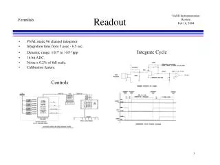
Temperature Readout. D r . Teerawat Thepmanee Automation Engineering, KMITL. Outline. Temperature readout Thermocouple readout RTD readout. Temperature Readout. Electrical signal. Output. Quantity. Readout. Sensors. Temperature Readout. Electrical signal. Output. Quantity.

Temperature Readout
E N D
Presentation Transcript
Temperature Readout Dr. TeerawatThepmanee Automation Engineering, KMITL
Outline • Temperature readout • Thermocouple readout • RTD readout Temperature readout
Temperature Readout Electrical signal Output Quantity Readout Sensors Temperature readout
Temperature Readout Electrical signal Output Quantity Readout Sensors Temperature readout
Temperature Readout Temperature readout
TC Sensor • TC sensor • Thermocouple • Temperature to Voltage or TC sensor Temperature readout
TC Readout • TC Readout • Voltage to Temperature • 1. Temperature Indicator (display) • - analog • - digital • 2. Temperature Transmitter (Signal) • signal transmission • - Pneumatic 3 to 15 psi • - Electrical signal 4 to 20 mA • - Electrical signal 4 to 20 mA + • Digital signal (HART) • - Digital signal (Fieldbus, Wireless Transmission) Display or K, C, F or % Signal Temperature readout
TC Readout Concept • TC Type s • J,K,N,T,E,R,S and B • etc. • Output • Display • Transmission I/P O/P • Measuring unit • Voltage meter • Compensations unit • Mechanical reference compensation • Fixed reference temp. • Electrical compensation • Conversion unit • emf to Temperature • - Scaling • - Polynomial equation • Signal condition • - V to I converter • - A to D converter Temperature readout
TC Readout Measuring unit Voltage from TC output KP V= VTM - VTR V Cu KN Temperature readout
Thermoelectric circuit KP KN TM= 100 C TR V Cu At TR = 25 C V = VTM– VTR = V100– V25 = 4.096 – 1.000 = 3.096 mV At TR = 0 C V = VTM– VTR = V100– V0 = 4.096 – 0.000 = 4.096 mV Temperature readout
TC Readout • Compensation unit • V = VTM - VTR • Mechanical reference compensation • Fixed reference temp. • Electrical compensation Temperature readout
Reference Junction • Mechanical Reference Junction Compensate • Fixed reference Junction Temperature (External reference Junction 0 C or 50C) • Electrical Reference Junction Compensate (Internal reference Junction) Temperature readout
I Mechanical Reference Compensate TR = 0 C 50 75 25 C 0 100 N S TR = 0 C TM= 100 C KP 4.096 mV KN Temperature readout
I Mechanical Reference Compensate TR = 25C 50 75 25 C 0 100 N S TR = 25C TM= 100 C KP 3.096 mV KN Temperature readout
I Mechanical Reference Compensate TR = 0 C 50 75 25 C 0 100 N S TR = 0 C TM= 100 C KP 4.096 mV KN Temperature readout
I Mechanical Reference Compensate TR = 0 C 50 75 25 C 0 100 N S TR = 25C TM= 100 C KP 3.096 mV KN Temperature readout
I Mechanical Reference Compensate TR = 25C 50 75 25 C 0 100 N S TR = 25C TM= 100 C KP 3.096 mV KN Temperature readout
Fixed Reference Temperature • Ice Pot • Ice Point cell • Oven Temperature readout
+ + Type-K TR _ _ Fixed Reference Temperature0 C Ambient 28 C Ambient 25 C Ambient 30 C Process 0C TM 24.905 20mA 600C 0.000 4 mA V = VTM -VTR V = VTM -VTR = V - V0 = V – V0 = 0.000 – 0.000 = 0.000mV = 24.905 – 0.000 = 24.905mV Temperature readout
+ + Type-K TR _ _ Fixed Reference Temperature50 C Ambient 28 C Ambient 25 C Ambient 30 C Process 0C 20mA TM 600C 22.882 -2.023 4 mA V = VTM - VTR V = VTM - VTR = V0 – V50 = V600 – V50 = 0.000 – 2.023 = -2.023mV = 24.905 – 2.023 =22.882mV Temperature readout
TA TM Type-K Electrical Compensation Ambient 25 C 600 C + 23.905 1.000 A/D 24.905 _ Compensate ROM Temperature readout
0.000 Transmitter + mV/ I Type-K _ Zero Span Electrical Compensation Ambient 0 C Ambient 30 C Process 600C TM 4 -20 mA 0C V = VTM – VTA+VC V = VTM – VTA+VC = V0 – V0+V0 = V600 – V0+V0 = 0.000 – 0.000+0.000 = 0.000mV = 24.905 – 0.000+0.000 = 24.905mV Temperature readout
1.000 Transmitter + mV/ I Type-K _ Zero Span Electrical Compensation Ambient 25 C Ambient 30 C Process 600C TM 4 -20 mA 0C V = VTM – VTA+VC V = VTM – VTA+VC = V0 – V25+V25 = V600 – V25+V25 = 24.905 – 1.000+1.000 = 24.905mV = 0.000 – 1.000+1.000 = 0.000mV Temperature readout
TC Readout • Conversion unit • V to C • - Scaling • - Polynomial eq. Emf (mV) 24.905 0 T(C) 0 600 T(C) 603 485 V(mV) 20.000 25.000 Temperature readout
TC Readout • Conversion unit • V to C • - Scaling • - Polynomial eq. Emf (mV) T = co + c1E +c2E2 + c3E3 + … + cnEn 24.905 0 T(C) 0 600 Temperature readout
TC Readout • Analog transmitter (4-20 mA) • HART transmitter (Analog + Digital) • Digital transmitter (Digital) Signal condition - V to I converter - A to D converter Temperature readout
RTD sensor • RTD sensor • Resistance Temperature Detector • Temperature to Resistance or RTD sensor Temperature readout
RTD Readout • RTD Readout • Resistance to Temperature • 1. Temperature Indicator (display) • - analog • - digital • 2. Temperature Transmitter (Signal) • signal transmission • - Pneumatic 3 to 15 psi • - Electrical signal 4 to 20 mA • - Electrical signal 4 to 20 mA + • Digital signal (HART) • - Digital signal (Fieldbus, Wireless Transmission) Display or K, C, F or % Signal Temperature readout
RTD Readout Concept • Input • PRT • Nickel • Copper • Output • Display • Transmission I/P O/P • Measuring unit • Ohm meter • - Wheatstone Bridge method • - Potentionmetric method • Conversion unit • Resistance to Temperature • - Scaling • - Inverse CVD • Signal condition • - V to I converter • - A to D converter Temperature readout
RTD Readout (Measuring unit) RTD Readout Measuring Unit (Ω) Conversion Unit(Ω to C) Signal condition I/P O/P Temperature readout
Resistance measurement Resistance measurement method • Potentionmetric method • Bridge method • etc. Temperature readout
Rs VRs VS R(t) VRt Potentionmetric method R(t) = ( VRt/ VRs ).Rs Temperature readout
Potentionmetric Readout P RTD Transmitter c RTD sensor 4-20 mA CCS V/ I c P RTD Transmitter RTD sensor Temperature readout
4-20 mA V/ I R1 R2 100 100 a I I b R3 RTD 100 100 RTD bridge Readout R1 RTD = R2 R3 100 100 = 100 100 1 = 1 Temperature readout
RTD Transmitter C 4-20 mA V/ I R1 R2 Temp. 0 C RTD RL1=1 100 100 100 R3 2-wire RTD RL2=1 RTD+ RL1+RL2 R1 = R2 R3 100 100 + 1 + 1 = 100 100 1 ≠1.02 2-wires RTD bridge Readout Temperature readout
RTD Transmitter C Temperature Effect of Lead Resistance 4-20 mA V/ I R1 R2 Ambient temp. Temp. 0 C RTD 100 100 RL1 100 R3 2-wire RTD RL2 Ambient 30C[RL1,RL2=2] Ambient 25 C[RL1,RL2=1] R1 RTD+ RL1+RL2 RTD+ RL1+RL2 R1 = = R2 R3 R2 R3 100 100 +2 + 2 100 100 + 1 +1 = = 100 100 100 100 1 ≠ 1.02 1 ≠ 1.04 2-wires RTD bridge Readout Temperature readout
RTD Transmitter C Temperature Effect of Lead Resistance 4-20 mA V/ I R1 R2 Ambient temp. Temp. 0 C RTD RL1 100 100 3-wire RTD 100 R3 RL2 Ambient 30C[RL1,RL2=2] Ambient 25 C[RL1,RL2=1] R1 RTD + RL1 R1 RTD + RL1 = = R2 R3 + RL2 R3 + RL2 R2 100 100 + 1 100 + 2 100 = = 100 100 + 1 100 100 + 2 1 = 1 1 = 1 3-wires RTD bridge Readout Temperature readout
Temperature Effect of Lead Resistance RTD Transmitter C 4-20 mA V/ I R1 R2 Ambient temp. Temp. 500 C RTD RL1 100 100 100 R3 RL2 Ambient 30C[RL1,RL2=2] Ambient 25 C[RL1,RL2=1] R1 RTD + RL1 R1 RTD + RL1 = = R2 R3 + RL2 R3 + RL2 R2 100 100 280.98 + 1 280.98 + 2 = = 100 100 + 1 100 100 + 2 1 ≠2.79 1 ≠2.77 2-wires RTD with 3-wires Transmitter Temperature readout
RTD Transmitter C Temperature Effect of Lead Resistance 4-20 mA V/ I R1 R2 Ambient temp. Temp. 0 C RTD RL1 100 100 100 RL2 R3 RL3 RL4 Ambient 30C[RL1,RL2=2] Ambient 25 C[RL1,RL2=1] R1 RTD + RL1+RL2 R1 RTD + RL1+RL2 = = R2 R3 + RL3+RL4 R3 + RL3+RL4 R2 100 + 1 + 1 100 + 2 + 2 100 100 = = 100 100 100 + 1 + 1 100 + 2 + 2 1 = 1 1 = 1 4-wires RTD bridge Readout Temperature readout
RTD Transmitter C Temperature Effect of Lead Resistance 4-20 mA V/ I R1 R2 Ambient temp. Temp. 500 C RTD RL1 100 100 100 RL2 R3 RL3 RL4 Ambient 30C[RL1,RL2=2] Ambient 25 C[RL1,RL2=1] R1 RTD + RL1+RL2 R1 RTD + RL1+RL2 = = R2 R3 + RL3+RL4 R2 R3 + RL3+RL4 280.98 + 1 + 1 280.98 + 2 + 2 100 100 = = 100 100 + 1 + 1 100 100 + 2 + 2 1 ≠2.77 1 ≠2.74 4-wires RTD bridge Readout Temperature readout
Error in Resistance measurement • Drift • Hysteresis • Leakage • Reactance • Lead Resistance • Thermoelectric emf. • Electromagnetic Interference (EMI) • Self heating • Stem Conduction Temperature readout
Drift • Drift :เกิดการเปลี่ยนแปลงค่าความต้านทานตามการเวลามีสาเหตุมาจาก Oxidation , contamination, หรือ Strain • ขจัดให้ลดน้อยหรือทำให้หมดไปด้วยการทำ Annealing ที่ถูกต้อง • ควรบันทึกผลเก็บไว้เพื่อดูทิศทางที่เปลี่ยนแปลง Temperature readout
Hysteresis • Hysteresisเกิดจากความเครียดใน sensing element • ความผิดพลาดมีสัดส่วนเพิ่มขึ้นตามอุณหภูมิ • ใน SPRT เกิดขึ้นน้อยมาก • ใน Secondary PRT มีค่าน้อยกว่า 10 mK • การจับอย่างระมัดระวัง จะช่วยลดปัญหาได้ Temperature readout
Leakage current and Reactance • Leakage :วัสดุที่ใช้ทำฉนวนบางชนิด มีความเป็นฉนวนที่อุณหภูมิต่ำแต่นำไฟฟ้าดีที่อุณหภูมิสูงๆ ทำให้กระแสไฟฟ้าไหลผ่านฉนวน • Reactance :จะเกิดขึ้นเมื่อวัดความต้านทานด้วย A.C. ดังนั้นควรใช้ความถี่ต่ำๆในการวัด Temperature readout
Lead resistance • Lead Resistance :ในการวัดแบบ 2 สายต้องระวังเรื่องความต้านทานสายด้วย • ตัวอย่างPRT sensitivity 0.004 / C, ที่ 0 CPRT=100 , 0.2 lead UT = (2x0.2)/(0.004x100) = 1 C Temperature readout
Self heating • Self heating :เกิดจากวิธีการวัดความต้านทานที่ต้องปล่อยกระแสไฟฟ้าเข้าไปใน Sensor ทำให้เกิดความร้อนที่ตัว sensor เอง • สามารถลดได้โดยการปล่อยกระแสไฟฟ้าแล้วหยุดปล่อย • หรือการลดกระแสที่ไหลผ่าน sensor ลงแต่จะมีผลกระทบจาก electrical noise และ EMI Temperature readout
current Self heating • T = I2r/ • ตัวอย่าง25 PRT 1mA 0.01 W/C • UT = (0.0012x25)/0.01 • = 0.0025 C Temperature readout
Thermoelectric EMF • Thermoelectric emf. :เกิดจากความแตกต่างของโลหะต่างชนิด เช่นจุดต่อระหว่าง Sensor กับ Terminal จะทำให้เกิดแรงเคลื่อนขึ้นเล็กน้อย Temperature readout
Stem Conduction • Stem Conduction :การสูญเสียความร้อนไปตาม sensor sheath • ความลึกในการจุ่ม = 20 x เส้นผ่าศูนย์กลาง + ความยาวเซนเซอร์ Temperature readout
Electromagnetic Interference (EMI) • Electromagnetic Interference (EMI) :เกิดการรบกวนจากภายนอก หรือ Ground loop ที่เกิดจากกระแสไฟฟ้าไหลผ่าน Sheath และ Cable Shield ที่มาจากศักดาทางไฟฟ้าที่ไม่เท่ากัน Temperature readout