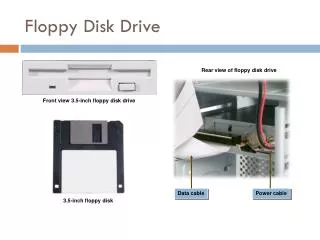
Floppy disks
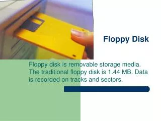
Floppy disks. The floppy disk drive ( FDD ) was invented at IBM by Alan Shugart in 1967. Floppy disk is a round ,flat, thin sheet of flexible Mylar impregnated with magnetic particles on both sides and permanently shielded in a plastic case. Main types are 8”,51/4”,31/2”.


Floppy disks
E N D
Presentation Transcript
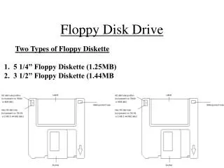
The floppy disk drive (FDD) was invented at IBM by Alan Shugart in 1967. • Floppy disk is a round ,flat, thin sheet of flexible Mylar impregnated with magnetic particles on both sides and permanently shielded in a plastic case. • Main types are 8”,51/4”,31/2”. • 51/4” comes in two varieties-high density(360KB) & double density(1.2 MB) • 31/2” comes in 3 varieties-doubledensity(740KB),high density(1.44MB) & very high density(2.88MB)
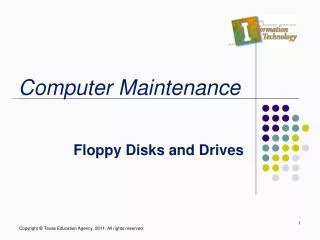
Floppy drive • It is a device which reads or write data to and from floppy disks. • The major parts of a floppy drive are 1.Read/Write head • Located on both sides of a diskette. 2.Drive motor • It spins at 300 rpm.
3.Stepper motor • This motor makes a precise number of stepped revolutions to move the read/write head assembly to the proper track position. • The read/write head assembly is fastened to the stepper motor shaft.
4.Mechanical Frame • A system of levers that opens the little protective window on the diskette to allow the read/write heads to touch the dual-sided diskette media. • An external button allows the diskette to be ejected, at which point the spring-loaded protective window on the diskette closes.
Circuit Board • Contains all of the electronics to handle the data read from or written to the diskette. • It also controls the stepper-motor control circuits used to move the read/write heads to each track, as well as the movement of the read/write heads toward the diskette surface.
Floppy drive controller • It is used for the communication between processor and floppy drive. • It is integrated to mother board using super I/O chip. • Floppy controller speed is rate at which data is transferred between processor and floppy disk. • 3 different controller speeds are: 250 kbps:supports high density 5.25”,double density 3.5” disks 500kbps:supports all disks except 2.88MB 3.5” disks.
1mbps:supports all floppy disks. Power cable • To connect floppy drive to power supply unit. • Requires 2 voltages: +5v for logic circuits. +12v for motors. • 4 pin connector is used. Control/Data cable • For transferring data and control signals. • It has 34 pins and 5 connectors.
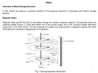
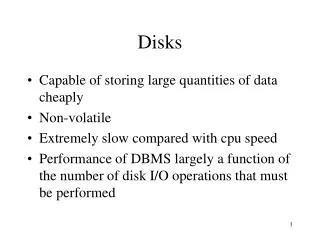
Hard disk drives It is a non volatile mass storage device. It consists of platters made of aluminum alloy or glass ceramic composite material. Platters are coated with magnetic material on both sides and stacked one on top of another. Platters are divided into concentric rings called tracks. Tracks are divided into sectors. Each sector contains 512 bytes of data. Each track is a part of a cylinder which consists of all the tracks in the same position on each platter surface.
Each sector has an address area and a data area. • The address area identifies the sector, the cylinder in which the sector resides, and the head used to access that sector. • The address area also contains CRC information. • Data area contains ECC ,several bytes of timing signals followed by actual data.
Clusters • Smallest unit of storage on a hard disk is cluster. • The size of a cluster depends on 2 factors. 1.)Size of the partition 2.)file system associated with the partition. • Clusters are also called allocation units. • A cluster can consist of one or more consecutive sectors.
Cylinder skewing • Difficulty in catching the 1st sector of next track during same rotation. • When the cylinders are skewed, the first sector of each track is offset from that of the next track by one sector.
Zoned bit recording • It is a technique that varies the number of sectors on each track. • Cylinders are split into a number of zones. Each of the tracks in a particular zone has the same number of sectors. • Outer zones have more sectors than inner zones.
Hard drive components • Platters • Read/Write Head • Head actuator • Spindle motor • Logic board
The functions of logic board include • Monitor the speed of spindle motor and adjust it when necessary. • Control the movement of actuator to the correct position. • Buffer data to and from the drive. • Control the timing of the drive’s read and write process. • Amplify the low voltage signals produced by the drive’s read process. • Receive and process power management directives from the main system.
Performance factors 1.Seek Time • It is the amount of time that the drive takes to move the heads from one track to another, measured in milliseconds. 2.Latency • It is the amount of time it takes for the platter to spin, bringing the sector to the right position. • Faster the platters spin, the lower the latency.
3.Access Time • It is the sum of average seek time and average latency measured in milliseconds. 4.Track Switch Time • It is the amount of time the actuator takes to move the head from one track to the next adjacent one. 5.Head Switch Time • It is the delay incurred when switching from one head to another without moving the actuator.
6.Rotational Speed • It specifies the speed at which the disk platters spin, in revolutions per minute(rpm). • Faster speed means reduced latency and faster internal transfer rates. 7.Internal Data Transfer Rate • The disk read process transfers data from the platters to the buffer and then from buffer to system memory. • Internal Data Transfer Rate is the speed at which data is transferred between platters and buffer.
8.Areal Density • It is the amount of data that can be stored on a particular area of the drive. • To compute the areal density ,multiply its linear bits per inch(BPI) by the drive’s track per inch(TPI). • It is measured in bits per square inch(BPSI).
The specifications that you see when buying a drive are: 1.Size or Capacity (specified in GB) 2. Spin Speed(Usually 7200rpm) 3.Interface (Usually SATA 3Gb/s or 6Gb/s) 4.Form factor or drive size (3.5”) 5.Size of buffer or cache memory(usually 32MB or 64MB)
IDE Interface • IDE stands for Integrated Drive Electronics. • Controller is built into the drive instead of being a separate unit. • Advantages of integrating controller into drive 1.Communication become efficient. 2.They do not have to be standardized.
ATA Standards • Commercial name of the interface for IDE drives is AT Attachment(ATA) interface named for the IBM AT computer that first introduced the 16 bit ISA bus. • Different versions are available 1.ATA 2.ATA-2 i)Fast ATA and fast ATA-2 ii)Enhanced IDE (EIDE) 3.ATA-3 4.ATA-4 5.ATA-5 6.ATA-6
ATA standard • It was proposed in 1988 but was not actually approved until 1994. • It uses a 40 pin cable to connect to the system bus. • It includes support for PIO modes 0,1, and 2, single word modes 0 and 1, and multiword DMA mode 0. • Drive capacity was limited to 504 MB. • It supports only 2 hard drives. • Uses CHS addressing.
ATA-2 standard • It supports PIO mode 3 and 4 and multiword DMA mode 1 and 2. • It introduces LBA, which can break the 504 MB hard disk barrier. • It introduces Identify Drive Instruction.
Fast ATA and fast ATA-2 • Seagate introduced ATA-2 under the names Fast ATA and fast ATA-2. • Fast ATA and Fast ATA-2 drives are same ,except that they support Fast ATA do not support PIO mode 4 or multiword DMA mode 2.
Enhanced IDE • It conforms to the ATA-2 standard with 2 important additions. • The first is the inclusion of two host adapters which supports 4 drives. • The second is the inclusion of ATA Packet Interface(ATAPI). • ATAPI standard provides support for devices other than hard disk drives.
ATA-3 • It introduces Self Monitoring Analysis and Reporting Technology(SMART). • Has security mode which allows devices to be protected with a password. • It does not support any new transfer modes.
ATA-4 • It supports Ultra DMA modes 0,1 and 2. • Supports Advanced Power Management(APM) developed by Intel and Microsoft in 1992. • Some improvements to the IDE cable for higher transfer rates.
ATA-5 • It supports UDMA 3 and 4. ATA-6 • Under development
Data Transfer Modes • Programmed Input/Output(PIO) • Direct Memory Access(DMA) • Ultra DMA
PIO mode • Oldest mode of transferring data in IDE interfaces.
Disk formatting • Disk formatting is the process of preparing a hard disk drive or flexible disk medium for data storage. • Two types of formatting 1.low level 2.high level
Low level formatting • It is also called physical formatting. • In Low level formatting all the cylinders, tracks and sectors of the disk are outlined. • When you buy a hard drive, it has already undergone low-level formatting. SO YOU DO NOT NEED TO PERFORM LOW-LEVEL FORMATTING.
Partitioning drives • Drive can have 1 to 24 logical drives. • Logical drives can be obtained by partitioning physical drive. • Reasons for partitioning are: 1.there must be at least one master boot partition on the drive in order to high level format the drive. 2.to install more than one OS and keep them on separate logical drives. 3.to install different file systems. 4.To keep other applications separate from OS.
High level formatting • Different file systems used are FAT16,VFAT,FAT32,NTFS etc. • File systems are tables that an OS uses to locate files on the disk. • It creates a file system on the disks that allow an OS to use the disk space to store and access files.