Floppy Disk Drive
Floppy Disk Drive. Two Types of Floppy Diskette 1. 5 1/4” Floppy Diskette (1.25MB) 2. 3 1/2” Floppy Diskette (1.44MB. Floppy Disk Drive. Recording format. Two types of recording formats used for storing data on the disks 1. Frequency Modulation (FM)


Floppy Disk Drive
E N D
Presentation Transcript
Floppy Disk Drive Two Types of Floppy Diskette 1. 5 1/4” Floppy Diskette (1.25MB) 2. 3 1/2” Floppy Diskette (1.44MB
Recording format Two types of recording formats used for storing data on the disks 1. Frequency Modulation (FM) 2. Modified Frequency Modulation (MFM) Frequency Modulation In this method every data bit cell starts with a flux transition. A clock is recorded at the beginning data bit cell. If a data bit “1” has to be written, a flux transition is recorded in the middle of a bit cell Modified Frequency Modulation In MFM, no clock (pulse) is recorded at the beginning of a bit cell. Similar to FM, a flux transition is recorded in the middle of a bit, if the data bit to be recorded is “1”. If a data bit “0” has to be written next to a data bit “1”, then no flux transition is recorded at all. If a current and a preceding data bits are zero only one pulse is recorded at the beginning of a bit cell. From the figure it is clear that we will be able to store double the data in the same area, if we use MFM recording format instead of F.M. The recording format is decided by the operating system. In MFM there is only one flux reversal per bit cell regardless of the data being “1” or “0”. For this reason twice as many bits can be recorded using the MFM method than the F.M. method. Hence the term Double Density is used, for MFM format of recording.
Clusters Clusters DOS rarely deals with individual sectors. But instead, data storage is done in group of sectors, called sectors. Depending on the diskette type, its format, and DOS version, the cluster varies.
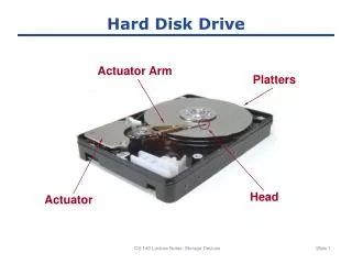
Floppy Disk Drive Read/Write head: A floppy disk drive normally has two-read/write heads making Modern floppy disk drives as double-sided drives. A head exists for each side of disk and Both heads are used for reading and writing on the respective disk side. Head 0 and Head 1: Many people do not realize that the first head (head 0) is bottom one and top head is head 1. The top head is located either four or eight tracks inward from the bottom head depending upon the drive type. Head Movement: A motor called head actuator moves the head mechanism. The heads can move in and out over the surface of the disk in a straight line to position themselves over various tracks. The heads move in and out tangentially to the tracks that they record on the disk. Heads are mounted on the same track, they move in unison and cannot move independently of each other.
Floppy Disk Drive Head: The heads are made of soft ferrous (iron) compound with electromagnetic coils. Each head is a composite design with a R/W head centered within two tunnel erasure heads in the same physical assembly. PC compatible floppy disk drive spin at 300 or 360 r.p.m. The two heads are spring loaded and physically grip the disk with small pressure, this pressure does not present excessive friction. Recording Method: Tunnel Erasure: As the track is laid down by the R/W heads, the trailing tunnel erasure heads force the data to be present only within a specified narrow tunnel on each track. This process prevents the signals from reaching adjacent track and making cross talk. Straddle Erasure: In this method, the R/W and the erasure heads do recording and erasing at the same time. The erasure head is not used to erase data stored in the diskette. It trims the top and bottom fringes of recorded flux reversals. The erasure heads reduce the effect of cross-talk between tracks and minimize the errors induced by minor run out problems on the diskette or diskette drive. Head alignment: Alignment is the process of placement of the heads with respect to the track that they must read and write. Head alignment can be checked only against some sort of reference-standard disk recorded by perfectly aligned machine. These types of disks are available and one can use one to check the drive alignment.
Floppy Disk Drive Coating: Newer disks are specially coated with Teflon or other compounds to further reduce friction and enable the disk to slide more easily under the heads. Because of the contact between the heads and the disk, a buildup of the oxide from the disk eventually forms on the heads. This buildup periodically can be cleaned off the heads. The Head Actuators: These mechanisms for floppy disk drive universally use a special kind of motor, a stepper motor, that moves in both directions, an amount equal to less than a single rotation. This type of motor does not spin around continuously. Each increment of motion or a multiple thereof defines each track on the disk. Steel band: The stepper motor usually is linked to the head rack by a coiled split steel band. The band winds and unwinds around the spindle of stepper motor translating rotary movement into linear movement.
Floppy Disk Drive Worm Gear Arrangement: Worm Gear Arrangementwith this type of head assembly rests on worm gear driven directly off the stepper motor shaft (worm gear arrangement are normally found on 31/2 inch drives. Most 48 tracks per inch(TPI) drives have motor that steps in increments of 3.6 degree. This means that each 3.6 degree of stepper motor rotation moves the heads from one track to the next. Most 96 TPI drives have a motor that moves in 1.8 degree increment which is exactly half of what the 48 TPI drive use. Average Access Time: is the normal amount of time the head spend moving at random from one track to another. The spindle motor: The normal speed of rotation either 300 or 360 r.p.m. depending upon the drive. The 5 ¼ inch high density drive spindle motor rotates at 360 r.p.m. The 5 ¼ inch double density drive spindle motor rotates at 300 r.p.m. The 3 ½ inch double density drive spindle motor rotates at 300 r.p.m. The 31/2 inch high density drive spindle motor rotates at 300 r.p.m. The 31/2 inch extra high density drive spindle motor rotates at 300 r.p.m.
Floppy Disk Drive Tachometer: The modern drives include an automatic tachometer control circuit that eliminates the need for adjustment of spindle motor speed. If the motor does not spin constantly at a specified speed, it becomes difficult to separate data from the MFM data read from the diskette. The Electronic Circuit Board: This PCB contains the circuitry of the following: Read/write heads Head actuator Spindle motor Disk sensor
Floppy Disk Drive Drive interface to the controller Read / Write circuits When a drive reads data from the disk media, the recorded flux reversals pass under the gap between the poles of the head and induce small voltage levels. These voltages are amplified by a read amplifier and send to a differentiator circuit. Unlike the analog recording system, here we don’t require an equalizer (used to boost high freq. and suppress low freq. signals). The differentiator circuit removes noise added to the recorded digital signal and restores recorded DC levels. Read/Write head and recording magnetic transition
Floppy Disk Drive The output of differentiator is fed to a comparator to get a square waveform. Then the square waveforms are fed to a zero crossing detector and one shot multivibrator. The one shot triggers, on both the positive and negative transitions, of the recovered signal. Thus the output of the read amplifier is converted into pulses for every voltage induced into the head by the flux reversals recorded on the disk. Similar to the read amplifier, we need a write amplifier also. It is basically a current switch that turns on current to transistors. When write enable signal comes, the current is turned on to the write driver transistors. When a data bit is present in the input, the current across the head changes polarity. Head Positioning Circuits Head positioning circuits contain the stepper motor driver. The controller provides step and direction signals to the drive. These step and direction pulses are applied to a bi-directional shift register. The shift register produces a train of pulses (4 pulses) in order to rotate the stepper motor in the clockwise direction. To rotate the motor in anti-clockwise direction, the pulse sequence has to be reversed. Applying the direction signal to the shift register can control the direction and the shift register shifts the pulses to right or left accordingly. The Power amplifier strengthens the output of the shift register before it is applied to the stepper motor.
Floppy Disk Drive Spindle Motor Control Spindle motor is a brush less motor. This motor’s stators have 6-pole, around which rotates a multi-pole magnetized ferrite disc. The motor contains 3 main coils and these are split into 6 poles in an eight-pole rotating ring magnet. There are 3 Hall IC’s which are solid-state magnetic field detectors, fixed at the center of 3 coils (in the stator assembly). The drive circuit, switches current into one coil at a time at the interval of 1200. The ferrite disc starts rotating, when one pair of coil pulls the ferrite disc while the next pair of coil pushes it, and the third pair is in inactive state. The position sensing Hall IC’s (3 in no.) are used to control the sequence of coil switching. Currents flow in both directions through the stators coils. There is a F.G (Frequency generator) inside the motor. The F.G produces frequency variations at its output, according to the speed variations. The frequency variations are converted into voltage variations by F-to-V converter. This output voltage is compared with a reference voltage and an error voltage is produced. This error voltage is used to correct the spindle motor speed continuously.
Sensors Sensors Disk drives contain several sensors. A sensor consists of Light Emitting Diode (LED) and a Photo Transistor. Normally the light from the LED falls on the base of the phototransistor and it comes on. Now the output from the phototransistor is low. If any object (like floppy disc or a flap attached to head assembly) comes between the LED and phototransistor, the light is blocked from falling on the base of the phototransistor. Now the output from phototransistor will be high. From the output of the phototransistor, we can sense that an object is present or absent. Index sensor: When the hole over the diskette (media) comes in alignment with the hole over its jacket (cover) it is sensed by the index sensor and a pulse is sent from the sensor. By sensing the index position, the drive is able to locate the beginning (first sector) of each track.
Sensors In 31/2” drive, the index sensor is not an optical sensor, as in the case of 5.25-inch drive. It uses the principle of Hall effect. This disk gets locked in the drive, by a pin inside the drive getting into a dip near the center of the disk. At one side of the spindle motor, there is a magnetic material coating. As the spindle motor rotates, the sensor by the side of the spindle, gives out the pulses. Track 0 sensor A flag is attached to the read/write assembly. When the head is exactly over track zero, the flag blocks the LED light from falling on the base of phototransistor. The output from the phototransistor is used by the drive controller circuit to identify whether the head is on track zero or not. Write Protect Sensor It is used to sense whether a diskette is write protected or not, by sensing whether the write-protect notch is closed or not. Write protect sensor is used to protect the important data stored in the diskette from the accidental erasures. The 1.2 MB and 1.44 MB drives have an additional sensor called “Disk Change Sensor”.
Sensors Disk Change sensor: In an AT system pin 34 of the disk drive interface is used to carry a signal called Disk Change. In an XT system this is not used. Drive Interface 1. 34-pin interface Power Connector 1. Molex power connector