Optimal Coupling Correction and Emittance Diagnostics for ATF2 Enhancements
130 likes | 255 Vues
This document outlines the progress and modifications implemented in the ATF2 extraction line for optimal coupling correction and emittance diagnostics. Key adjustments include transitioning to rectangular bends for improved field stability, extending diagnostic sections for better measurements, and recommending configurations to reduce coupling phases affecting emittance. A focus on optimizing the skew quadrupole arrangement, wire scanner placements, and additional diagnostic equipment is emphasized to achieve enhanced beam performance in particle accelerators.

Optimal Coupling Correction and Emittance Diagnostics for ATF2 Enhancements
E N D
Presentation Transcript
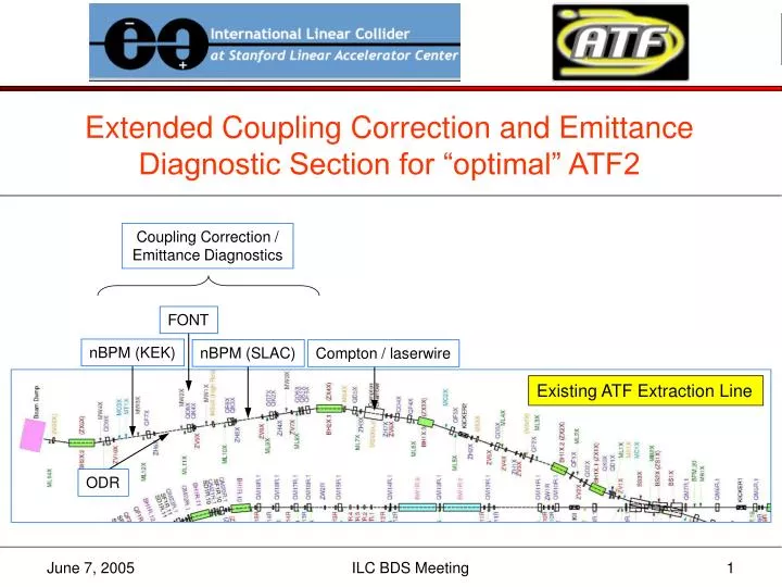
Extended Coupling Correction and Emittance Diagnostic Section for “optimal” ATF2 Coupling Correction / Emittance Diagnostics FONT nBPM (KEK) nBPM (SLAC) Compton / laserwire Existing ATF Extraction Line ODR ILC BDS Meeting
FF Optics Modifications From Tauchi-san’s email ([bds 117] June 2, 2005): 5. Optics modifications: (1) concentrate on "optimal" design (straight) … done (2) change bends from sector bends to rectangular … done (3) use 0.8 m bends (as used in ATF) instead of 1 m for better field stability and more space … done (4) remove octupoles (do not use them, and they are tight) … done (OC0 removed; OC1 moved away from SF1) (5) extend diagnostics section (use up to ~10 m additional space) … done (6) QM14 is the strongest quad, and is close to max field of BT quads, need to check if its strength can be reduced by reoptimizing the matching section … done(QM14[K1L] = -1.1 m-1) ILC BDS Meeting
β*x,y = 4,0.1 mm ΔL = 7.1 m (w.r.t. baseline) 30 cm offset ILC BDS Meeting
Assembly Hall optimal baseline ILC BDS Meeting
+1% -1% ILC BDS Meeting
Coupling Correction • ideally • correction section with 4 independent skew quadrupoles, followed by • 2D (4 wire scanner) emittance measurement section • optics for orthogonal control of the 4 coupling phases • minimize εy once with each skew quadrupole • in present ATF extraction line • non-optimal optics in EXT straight section • wire scanners and skew quads interspersed • each wire scanner has x, y, and “u/v” (small angle, ~10°) wires • one attempt at full 4D beam matrix measurement and correction was inconclusive1 1 See http://atfweb.kek.jp/atf/Reports/ATF-99-01.pdf ILC BDS Meeting
“Ideal” skew correction / ε diagnostic section SQ SQ SQ SQ WS WS WS WS – x – y 90° 90° 180° 90° 90° 90° 45° 45° 45° 45° 45° 45° See http://www.slac.stanford.edu/cgi-wrap/getdoc/slac-pub-8581.pdf ILC BDS Meeting
SQ SQ SQ SQ 2.0 2.0 2.0 2.0 2.0 2.0 2.0 2.0 2.0 1.3 1.3 1.3 1.3 WS WS WS WS WS – x – y 90° 90° 180° 90° 90° 90° 33° 57° 57° 33° 33° 57° 57° 33° 59.2 10.8 108.0 5.9 59.2 10.8 108.0 5.9 59.2 10.8 σ (μm) For MAD files see http://www.slac.stanford.edu/~mdw/ATF2/optimal ILC BDS Meeting
new quadrupole (between QF3X and BH1X.3) ILC BDS Meeting
A ‘Drift’ e-Diagnostic Section from Paul Emma … b s L w1 w2 w3 3 wire scanners (or profile monitors) ILC BDS Meeting
– x – y σmin = 3 μm ILC BDS Meeting
Continuing Work • optimize system bandwidth and performance • add BPMs and dipole correctors • simulate steering and dispersion/coupling correction with machine/diagnostic errors • verify what space is needed for diagnostic equipment in chicane • investigate drift ε–diagnostic section • writeup for ATF2 proposal document ILC BDS Meeting