Delay Analysis and Power Optimization in Buffer Chains and Logic Circuits
This document explores delay analysis and power consumption in buffer chain circuits, emphasizing the role of parasitic capacitance. It discusses how loading and power efficiency impact performance in various logic families including Complementary Pass Transistor Logic (CPL) and Domino Logic. The text outlines techniques for input pin ordering to minimize power dissipation and improve circuit performance during transitions. It also delves into methodologies for reducing unnecessary transitions in sequential and combinational logic, aiming to optimize power usage across integrated circuit designs.

Delay Analysis and Power Optimization in Buffer Chains and Logic Circuits
E N D
Presentation Transcript
L 18 : Circuit Level Design 성균관대학교 조 준 동 교수 http://vlsicad.skku.ac.kr
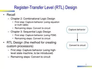
Delay analysis of buffer chain Delay analysis considering parasitic capacitance,Cp Buffer Chain Ck,Pk: stage k buffer output의 total capacitance, power PT: buffer chain의 power consumption Pn: load capacitance CL의 power consumption Eff: power efficiency pn/pT
Determining rise/fall time Slew Rate
Slew Rate(Cont’d) • Power consumption of Short circuit current in Oscillation Circuit
Reducing Area/Power Macro cell(Large part in chip area) XOR/XNOR/MUX(Primitive) Pass Tr. Logic Not using charge/discharge scheme Appropriate in Low Power Logic Pass Tr logic Family CPL (Complementary Pass Transistor Logic) DPL (Dual Pass Transistor Logic) SRPL (Swing Restored Pass Transistor Logic) CPL Basic Scheme Inverter Buffering Pass Transistor Logic
DPL Pass Tr Network + Dual p-MOS Enables rail-to-rail swing Characteristics Increasing input capacitance(delay) Increasing driving ability for existing 2 ON-path equals CPL in input loading capacitance SRPL Pass Tr network + Cross coupled inverter Restoring logic level Inverter size must not be too big Pass Transistor Logic(Cont’d)
Using Precharge/Evaluation scheme Family Domino logic NORA(NO RAce) logic Characteristics Decreasing input loading capacitance Power consumption in precharge clock Increasing useless switching in precharging period Basic architecture of Domino logic Dynamic Logic
Reorder the equivalent inputs to a transistor based on critical path delays and power consumption N- input Primitive CMOS logic symmetrical in function level antisymmetrical in Tr level capacitance of output stage body effect Scheme The signal that has many transition must be far from output If it is hard to estimate switching frequency, we must determine pin ordering considering path and path delay balance from primary input to input of Tr. Example of N-input CMOS logic Input Pin Ordering Experimentd with gate array of TI For a 4-input NAND gate in TI’s BiCMOS gate array library (with a load of 13 inverters), the delay varies by 20% while power dissipation by 10% between a good and bad ordering
VDD A B C D MPD MPA MPB MPC CL 1 1 A MNA CB 1 1 1 1 B MNB CC 1 1 1 1 C MNC CD 1 1 D MND (a) (b) (c) (d) INPUT PIN Reordering Simulation result ( tcycle=50ns, tf/tr=1ns) : A가 critical input인 경우 =38.4uW, D가 critical input인 경우 =47.2uW
Example Definition sensitization : input signal that forces output transition event sensitization vector : the other inputs if one signal is sensitized Sensitization
Considering Sensitization in Combinational logic:Remove unnecessary transitions in the C.L Considering Sensitization in Sequential logic: Also reduces the power consumption in the flip-flops. Sensitization(Cont’d)
TTL level signal CMOS input Characteristic Curve of CMOS Inverter TTL-Compatible
CMOS output signal TTL input Because of sink current IOL, CMOS gets a large amount of heat Increased chip operating temperature Power consumption of whole system TTL Compatible(Cont’d)
INPUT PIN Reordering • To reduce the power dissipation one should place the input with low transition density near the ground end.(a) If MNA turns off , only CL needs to be charged(b) If MND turns off , all CL, CB, CC and CD needs to be charged (c) If the critical input is rising and placed near output node, the initial charge of CB, CC and CD are zero and the delay time of CL discharging is less than (d) (d) If the critical input is rising and placed near ground end, the charge of CB, CC and CD must dischagge before the charge of CL discharge to zero