UML
50 likes | 199 Vues
UML . UML: Unified Modeling Language UML has many components to graphically model different aspects of an entire software system UML Class Diagrams correspond to E-R Diagram, but several differences. Summary of UML Class Diagram Notation. UML Class Diagrams (Contd.).

UML
E N D
Presentation Transcript
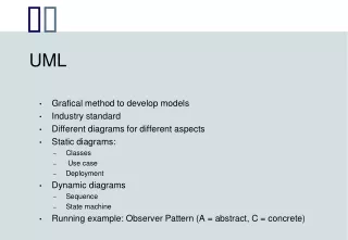
UML • UML: Unified Modeling Language • UML has many components to graphically model different aspects of an entire software system • UML Class Diagrams correspond to E-R Diagram, but several differences.
UML Class Diagrams (Contd.) • Entity sets are shown as boxes, and attributes are shown within the box, rather than as separate ellipses in E-R diagrams. • Binary relationship sets are represented in UML by just drawing a line connecting the entity sets. The relationship set name is written adjacent to the line. • The role played by an entity set in a relationship set may also be specified by writing the role name on the line, adjacent to the entity set. • The relationship set name may alternatively be written in a box, along with attributes of the relationship set, and the box is connected, using a dotted line, to the line depicting the relationship set. • Non-binary relationships drawn using diamonds, just as in ER diagrams
UML Class Diagram Notation (Cont.) overlapping disjoint *Note reversal of position in cardinality constraint depiction *Generalization can use merged or separate arrows independent of disjoint/overlapping
Cardinality constraints are specified in the form l..h, where l denotes the minimum and h the maximum number of relationships an entity can participate in. Beware: the positioning of the constraints is exactly the reverse of the positioning of constraints in E-R diagrams. The constraint 0..* on the E2side and 0..1 on the E1 side means that each E2 entity can participate in at most one relationship, whereas each E1 entity can participate in many relationships; in other words, the relationship is many to one from E2 to E1. Single values, such as 1 or * may be written on edges; The single value 1 on an edge is treated as equivalent to 1..1, while * is equivalent to 0..*. UML Class Diagrams (Contd.)